AT&SF Class 5001 Sand Dome – Boiler Feeds
Moving toward the rear on top of the boiler, I will be addressing the detailing on top of the sand dome in this segment. I will then make necessary changes to the boiler feed piping including the hot water pump, which has to be replaced. There are 16 photos attached to this email illustrating the work I’ve done this go around.
In photo Sand Dome-1, I have pointed out all the errors on the top of the sand dome.
sand dome 1 ⤵
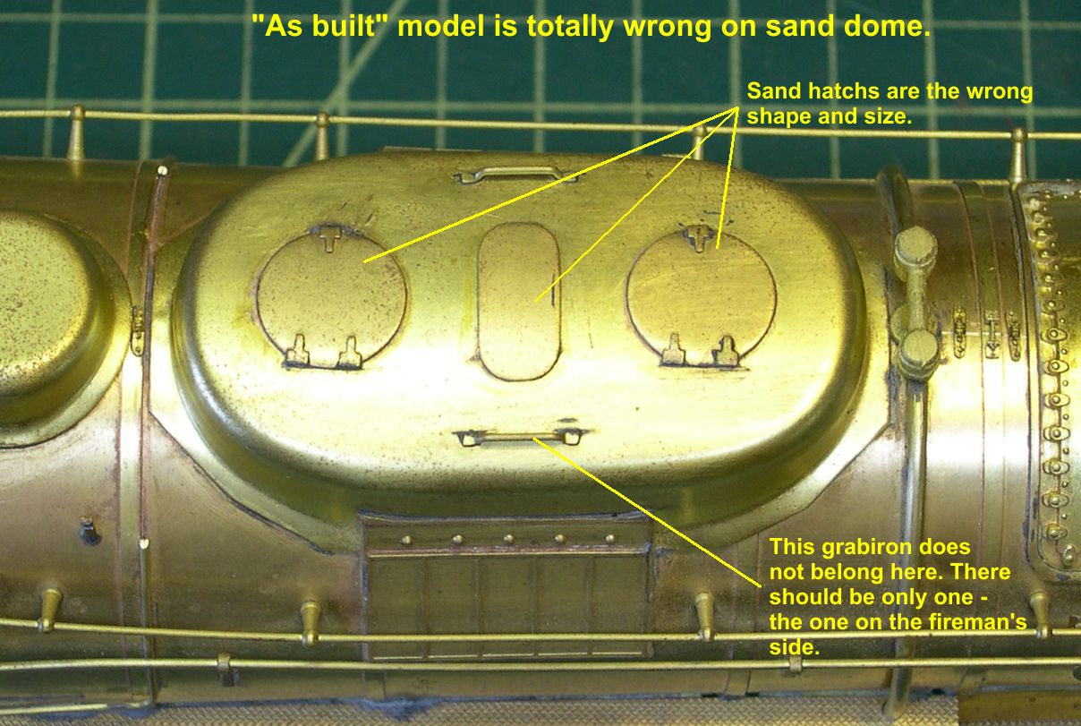
The only correct item is the grabiron on the fireman’s side. I started by stripping everything off the top of the dome, removing the excess solder, and sanding the surface nice and smooth. On one of the models, there were some scratches and tiny wrinkles from the forming of the dome along both sides, so I had to sand the sides smooth, too, as shown in photo Sand Dome-2.
sand dome 2 ⤵

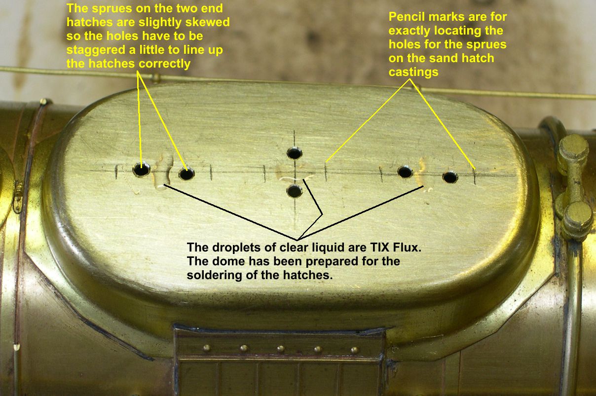
Then I carefully laid out the positions of the new custom ATSF sand hatch castings and located and drilled the holes for the sprues. There are actually two different sizes involved. The center sand hatch is slightly longer and slightly narrower than the end hatches, although they look very similar. Also, the sprues on the end hatches are offset just a little from the center line, so I had to compensate for that as shown in photo Sand Dome-3.
sand dome 3 ⤵
Soldering these sand hatches into position proved to be a challenge, as you cannot get to the bottom side of the sand dome top and the hatches actually sit up off the surface slightly. To solve this problem, I first put a touch of TIX Flux on the bottom sides of the hatches and deposited a small amount of solder on them as shown in photo Sand Dome-4.
sand dome 4 ⤵
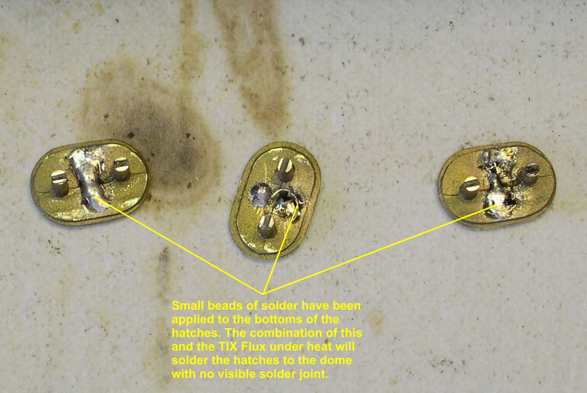
That photo also shows the sprues that go into the holes in the sand dome top to locate the hatches accurately. I then put a small amount of TIX Flux on the dome where the hatches will be sitting. Then I placed the hatches in position sitting up slightly on the solder bumps. I then used the heat gun to heat up the hatches and dome to the melting point of solder. Due to the TIX Flux, the solder immediately flowed and the hatches settled into position. Once cooled, the hatches were firmly soldered in place without a trace of a solder joint anywhere. Gotta remember this trick for the future . . .
Photos Sand Dome-5 and Sand Dome-6 show the completed sand dome top after the one correct grabiron was soldered in place.
sand dome 5 ⤵

sand dome 6 ⤵
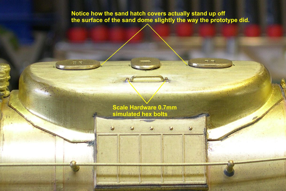
I used Scale Hardware 0.7mm simulated hex bolts for the ends of the grabiron. By the way, There are only small steps on the boiler on the fireman’s side for getting up to the sand dome, so it makes all the sense in the world for there to only be the one grabiron. I guess engineers were not competent to fill sand domes. This fireman’s side only access to the sand dome was common practice on both the ATSF and the SP.
The photo Boiler Feeds-1 shows how crudely the boiler feed pipes were connected to the top mounted check valves.
boiler feed 1 ⤵
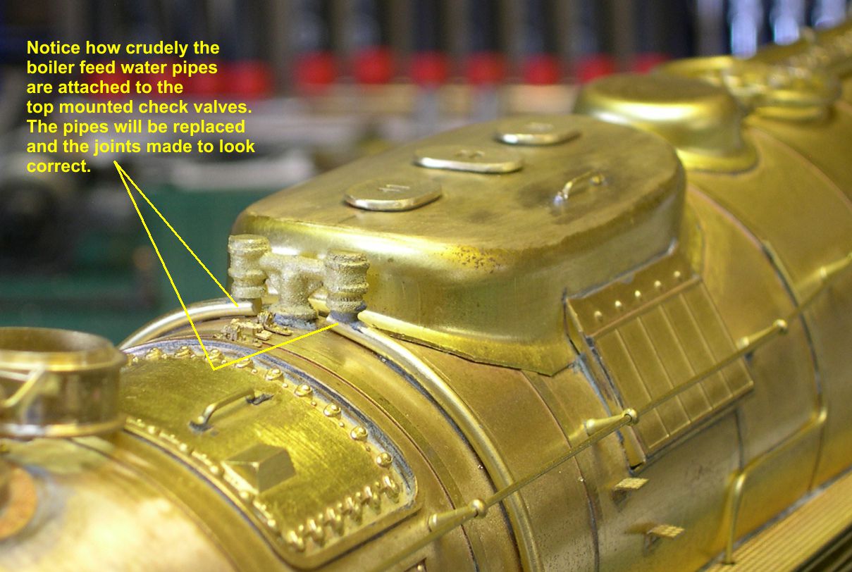
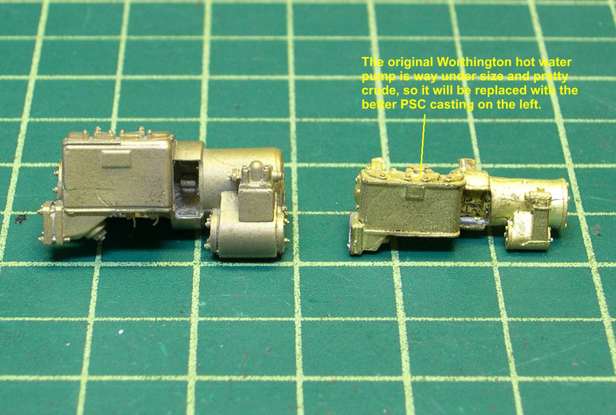
Both pipes need to be replaced anyway, as they run slightly differently on the 5001 vs the 5011 class engines. So I removed the two pipes, one from the injector and one from the Worthington hot water pump, and cleaned up the excess solder. Since I was fooling around with the hot water pipe anyway, it made sense to replace the hot water pump as well. As I examined it, I realized it was poorly placed on the boiler and was much too small, never mind the crude casting. Photo Boiler Feeds-2 shows the comparison between the original, under-sized pump and the new PSC casting to replace it.
boiler feed 2 ⤵
boiler feed 3 ⤵
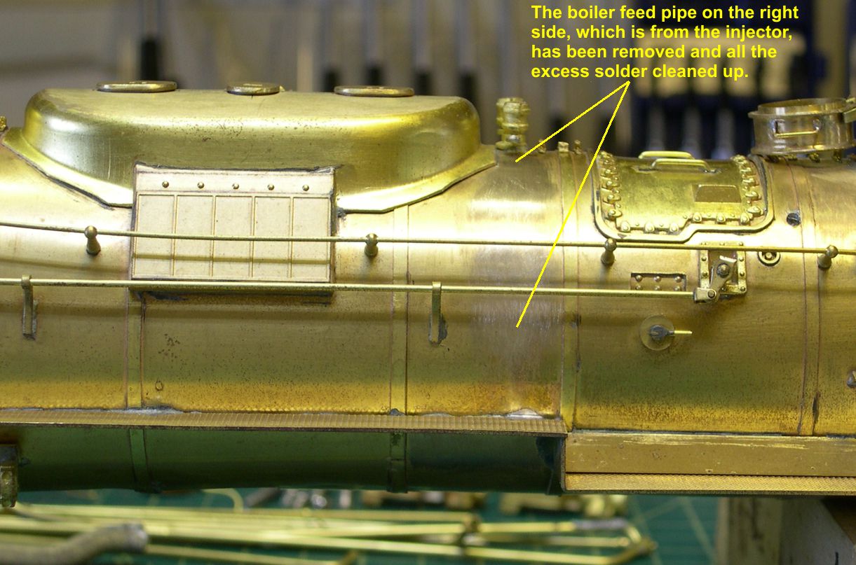
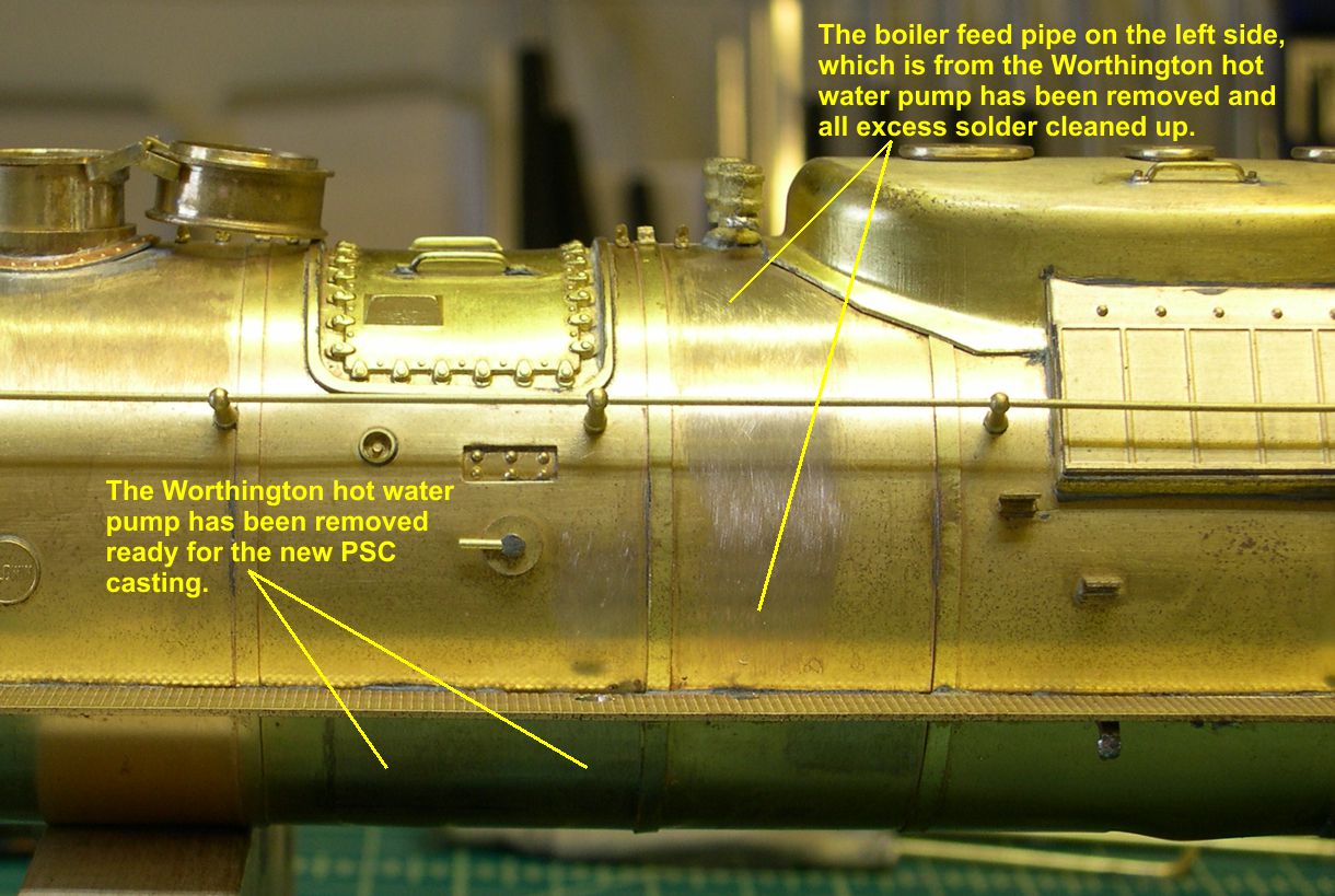
Photos Boiler Feeds-3 and Boiler Feeds-4 show the stripped areas of the boiler after clean up.
boiler feed 4 ⤵
The hot water pump was very nearly a project in and of itself. There is quite a bit of detailing that needs to be added. Photos Boiler Feeds-5 and Boiler Feeds-6 shows the added detailing.
boiler feed 5 ⤵
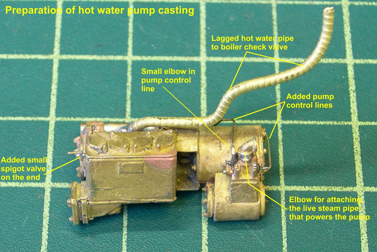
boiler feed 6 ⤵
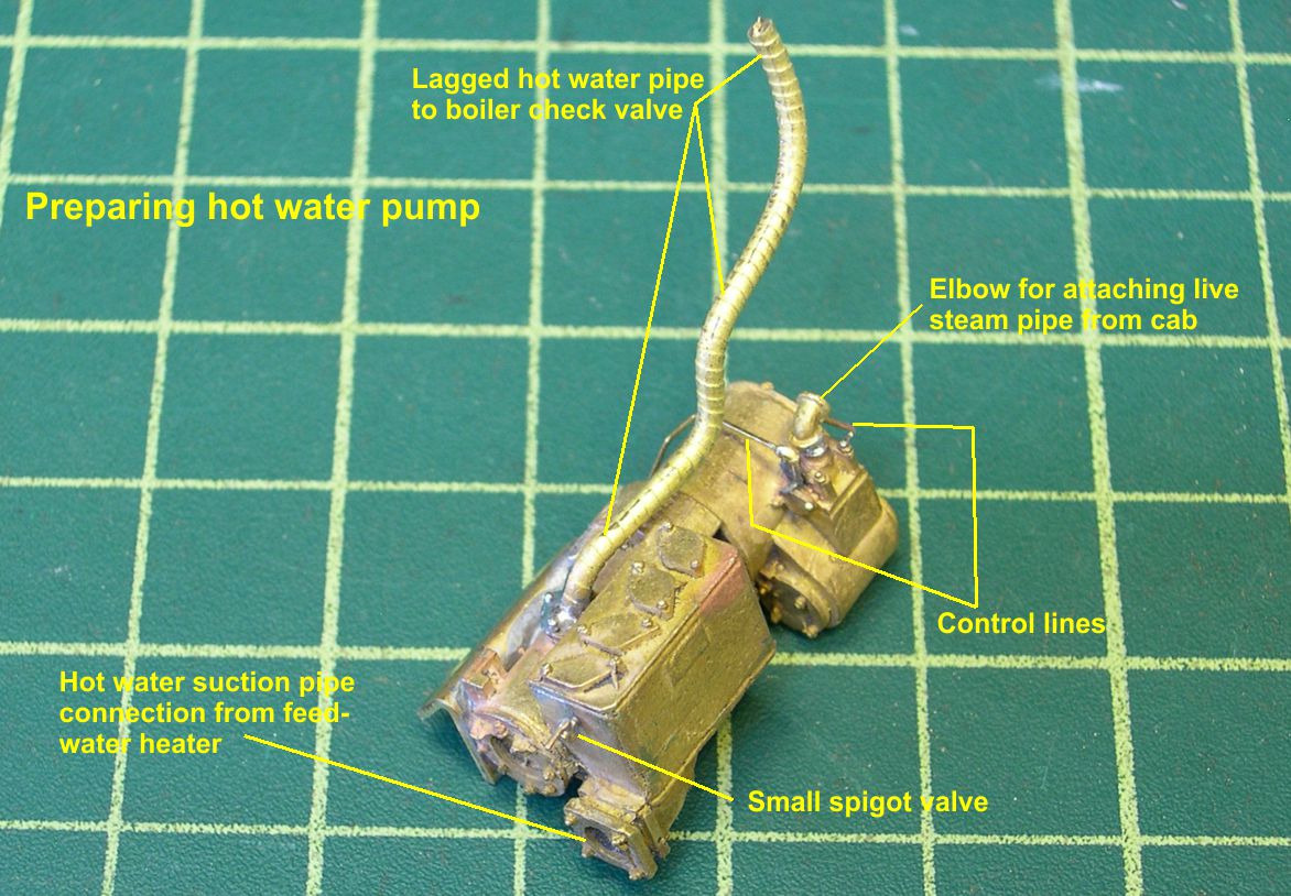
The two tiny pipes on the right side of the pump are the control lines for the pump. Those are rarely included in any model. One of them has a tiny pipe elbow prominently shown on top, so I had to drill out 0.018″ diameter holes in it for 0.015″ wire and solder that pipe together. The much larger pipe elbow between the two control lines will receive the lagged steam pipe for powering the pump. On the top rear of the pump is the outlet for the lagged hot water pipe to the check valve. This lagged pipe was a really miserable thing to get bent just right. Finally, there was a small spigot or drain valve on the front of the pump body. In photo Boiler Feeds-7, you can see how the new hot water pump fits on the model.
boiler feed 7 ⤵
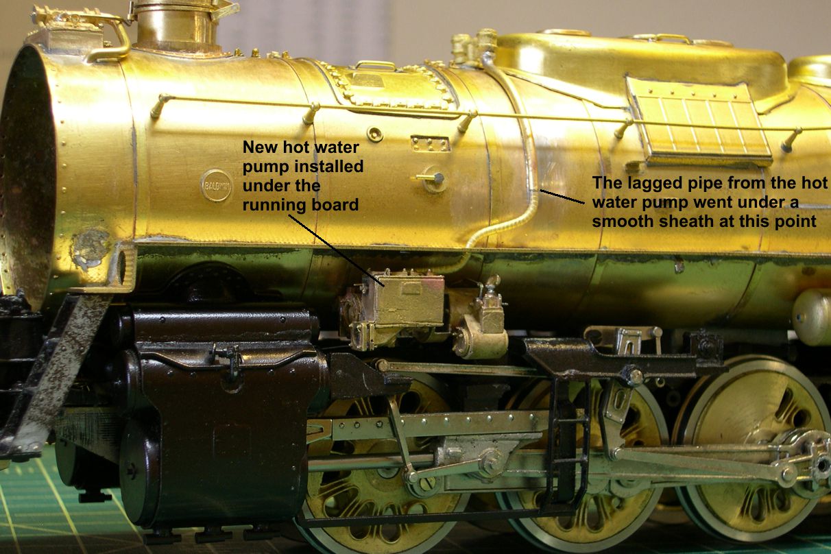
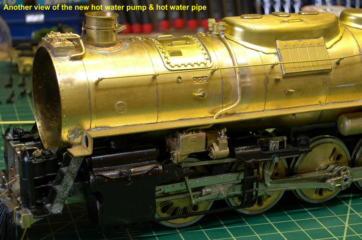
The pipe coming down from the check valve is slightly greater in diameter than the lagged pipe from the pump. This is because the lagged pipe went into a smooth shell as it went vertical. Not only do you have to get the pump in exactly the right place on the boiler, but you have to make the lagged pipe match up perfectly to the smooth shell pipe before soldering anything in place, as adjustments afterwards would be very difficult at best. Now you can see why this hot water pump is nearly a project all by its self. The photo Boiler Feeds-8 is another view of the hot water pump installation.
boiler feed 8 ⤵
In the photo Boiler Feeds-9, the cold water pipe from the injector has been replaced.
boiler feed 9 ⤵

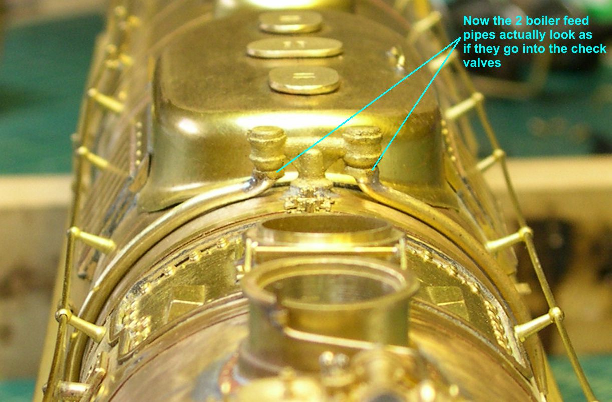
It barely goes through the hole in the running board on the left. The rest of the pipe will be installed later. It is too long and complicated to do the whole thing in one piece. Photo Boiler Feeds-10 shows how the boiler feed pipes now appear to go up into the check valves the way they should.
boiler feed 10 ⤵
After the challenges on this segment, I think I’ll just go have a beer and relax a bit. I can decide later what to approach next.