AT&SF Class 5001 Frame Adjustments 2
In the last part of this essay, I ended with the re-joined frame. This part begins with replacing all the parts I had to remove from the front of the frame. First though, there is supposed to be an 8″ diameter hole in the frame just behind the pilot beam. This may look straightforward, but don’t try just drilling this straight out. The curved surface and fairly thin material requires a careful procedure so the drill bit does not “grab” the material and tear it. I started with about a #42 bit and drilled the center of the hole. I then stepped up the size of the drill bits until I was fairly close to the required 0.167″ diameter. I then went bit by bit, manually with a hand held chuck, instead of skipping sizes, so I was barely removing any material. That allowed me to accomplish a very smooth hole with no nicks or distortions as you can see in the photos.
After drilling the hole in the frame, I cleaned up all the excess solder on the parts I had removed from the front of the frame. See photo 27.
photo 27 ⤵
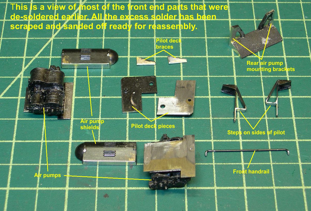
Reassembly of those parts is pretty easy since the scars show you where each part was soldered on. I did have to use my heat gun trick on most of the parts, since they are attached to the heavy brass frame. See photo 28 for how the two models look after replacement of the removed parts.
photo 28 ⤵
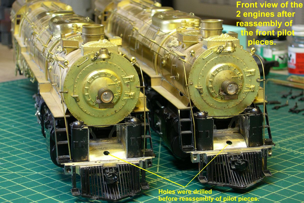
I did not replace the handrail and cut lever posts on the pilot beam yet, as they might get in the way of work necessary right behind them. These models are clearly 5001 class engines now, quite distinct from the 5011 class.
The next job to be undertaken is the new air pump mounting brackets for the front of the pilot deck. The old 5011 brackets are not even close due to the different dimensions of the pilot deck. On the face of it, these brackets look pretty simple – just a “V” shape with a few details attached. However, I quickly discovered that trying to do these manually was a waste of time. That “V” in the middle is very tough to get right since you can’t get a file in there more than about 2/3rds of the way toward the point. Also, these brackets are right up front and highly visible. They have to be exactly identical, or the human eye will notice the differences immediately. I finally gave up on cutting and filing these pieces and decided to use my mill to cut the shapes out very accurately. I used a trick I have used before of starting with thick material, cutting out the outline on the mill, then slicing off the required parts to the correct thickness. It is really easy to get identical parts this way. Starting with photo 29, I show how I made the brackets using that trick.
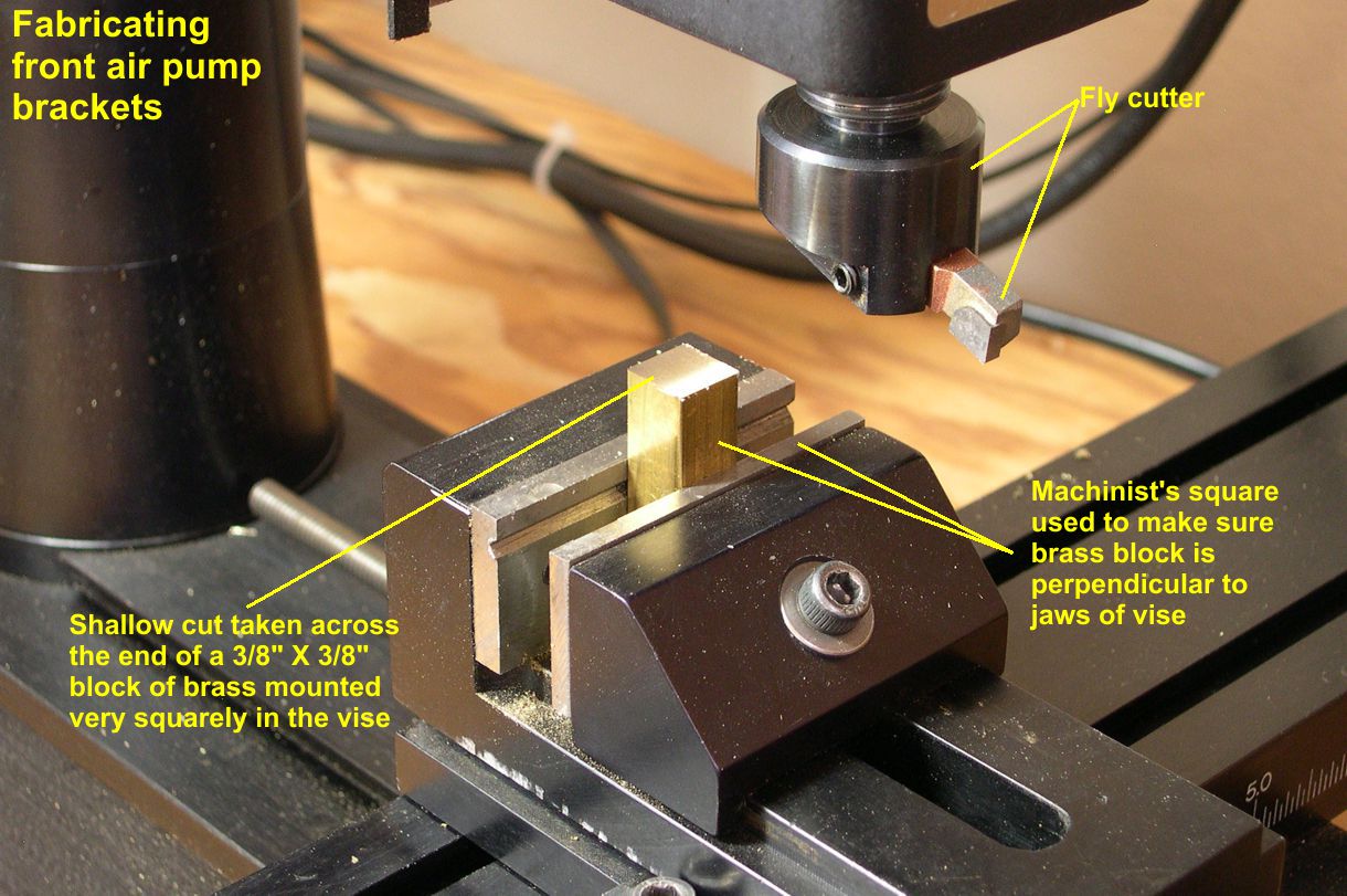
The first step is to cut off a piece of 3/8″ X 3/8″ brass bar stock somewhat longer than the brackets are tall. I then clamped this vertically in the machinist’s vise using a machinist’s square to make certain it was exactly perpendicular to the jaws of the vise. The fly cutter is ideal for the next few steps. I took a light cut across the top end of the brass block to make it smooth and square to the block. All this is shown in photo 29.
photo 29 ⤵
I then remounted the block as shown in photo 30 using machinist’s parallel bars to position the bock precisely relative to the bottom of the vise.
photo 30 ⤵
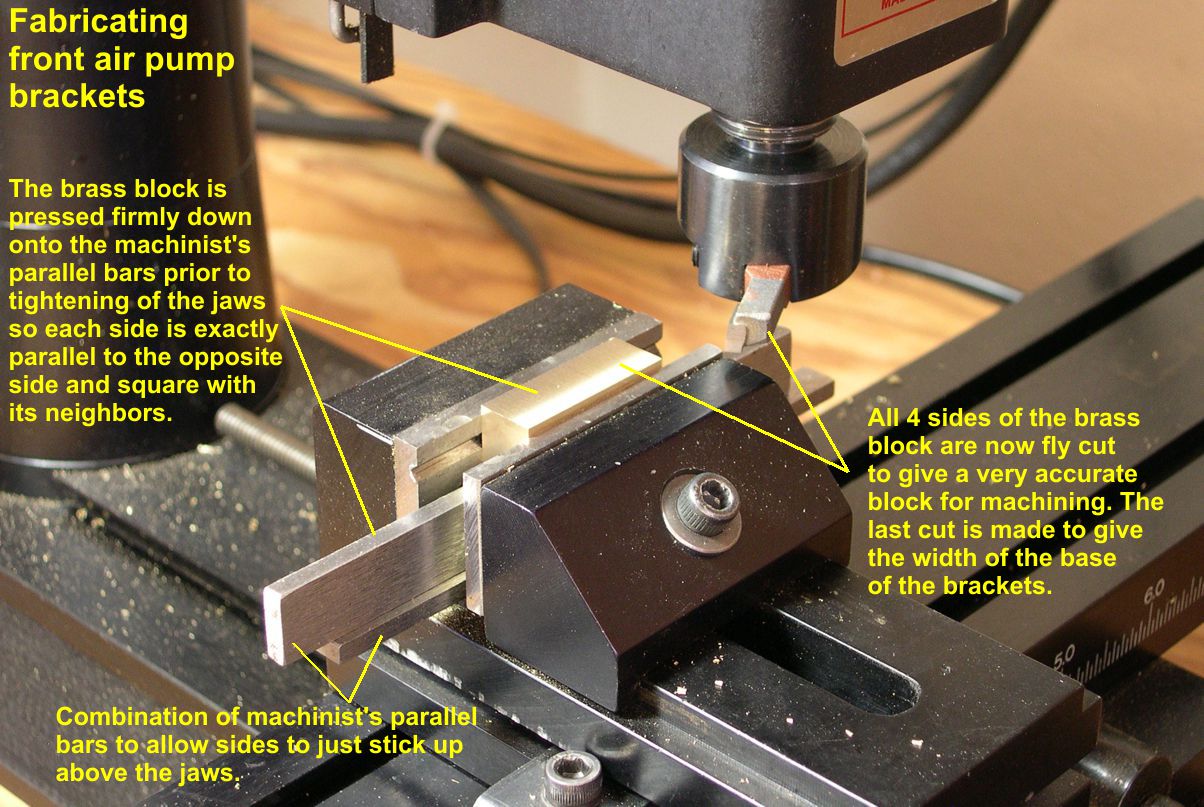
Another light cut across the side of the block leaves a nice smooth accurate surface. I did the same for each side of the block to produce a very accurate starting point. On the last side, I cut down far enough that the thickness of the block in that direction was equal to the width of the base of the desired brackets – the distance across the open end of the “V” of the brackets.
Now we start really shaping the brackets. The angle of the sloped side of the brackets is about 21 degrees. The easiest way to cut that angle is to mount the block at 21 degrees angle from the jaws of the vise and use the fly cutter to cut the angled side. But how do we know when to stop cutting? I used a simple trick. I measured the height of the brackets and scribed a line across the block that far from the finished end. As the fly cutter removes material, it makes it look as if the angled side is growing toward the scribed line. As I approached the scribed line, I took smaller and smaller bites with the fly cutter until the angled side exactly hit the line. Now the outside dimensions of the brackets are completed. See photo 31 for details on this operation.
photo 31 ⤵

Cutting the “V” in the middle is not a job for the fly cutter. I switched attachments to my slitting saw. I chose a 0.018″ thick blade so I would not get a perfectly pointy end to the “V”. It really should be very slightly rounded. These brackets were actually cast integral with the frame, and castings don’t have real sharp edges unless they are machined afterwards. Photo 32 shows how I clamped the shaped part of the block in the vise and cut off the excess material with the slitting saw. This makes the height of the brackets correct. In photo 33, you can see how I used the slitting saw to cut out the “V” in the middle of the brackets. After the “V” is cut out, I just mounted the block as if the brackets were stacked vertically and sliced off each bracket from the original block like slices of bread. Now I had 4 identical brackets.
photo 32 ⤵
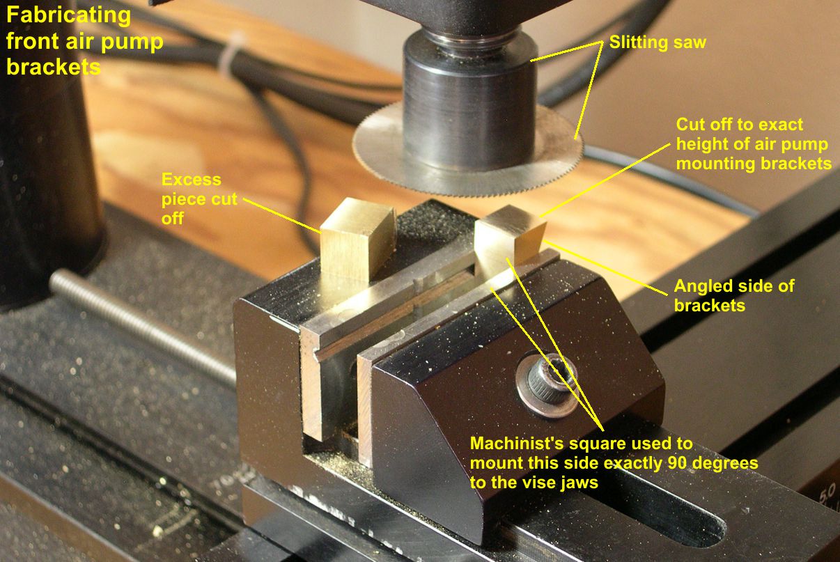
photo 33 ⤵
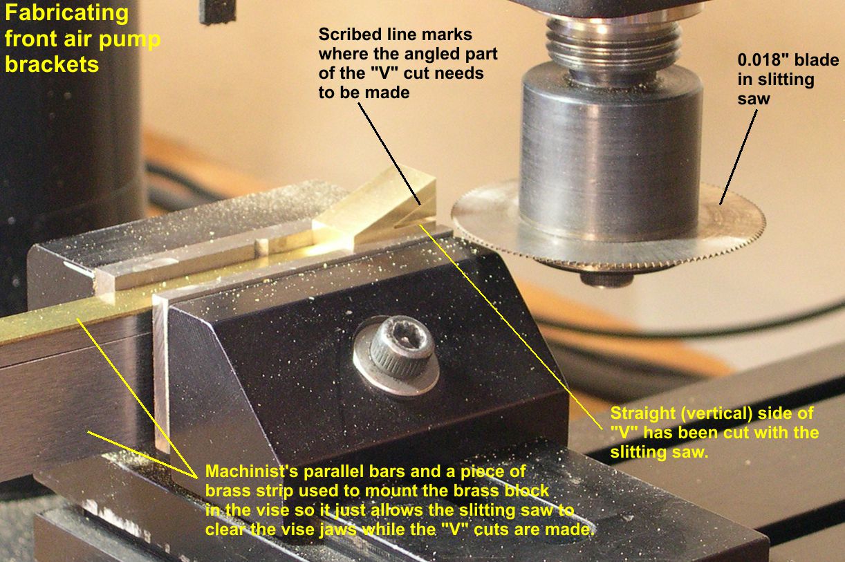
Photo 34 shows the 4 brackets after a little finishing work has been done on them.
photo 34 ⤵
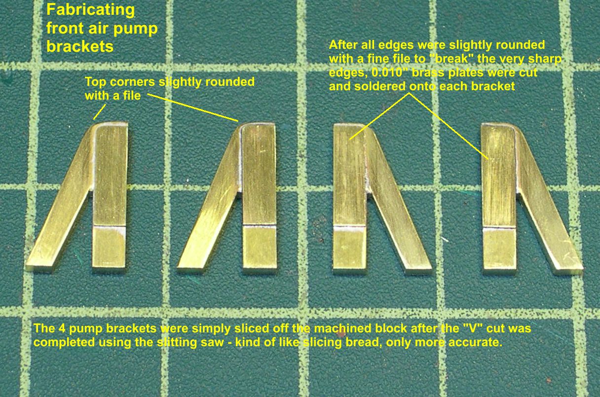
Right after slicing off from the original block, each bracket has unrealistically sharp edges. I used a fine file to “break” the edges as it is referred to in machining. Basically, you just file each edge slightly rounded. One top corner was also very rounded as shown in photo 34. I did that with a file, too. There were plates bolted to the brackets on their straight vertical sides, probably having to do either with mounting the air pumps or mounting the shields around the pumps. I can’t find a good enough photo to tell exactly what they are used for, but they are very visible. I cut them out of 0.010″ brass strip and soldered them in place as shown in photo 34. In photo 35, I have drilled holes and soldered in 0.5mm simulated hex bolts from Scale Hardware to complete the brackets.
photo 35 ⤵
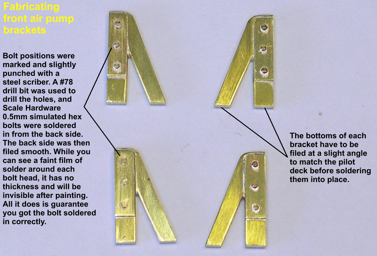
By soldering in the bolts from the back side, I had no cleanup to do on the front side. The only thing left to do on the brackets is to file a slight slant on the bottoms of the feet so they match the slope of the pilot deck.
Photo 36 shows the air pump mounting brackets installed on the pilot deck.
photo 36 ⤵
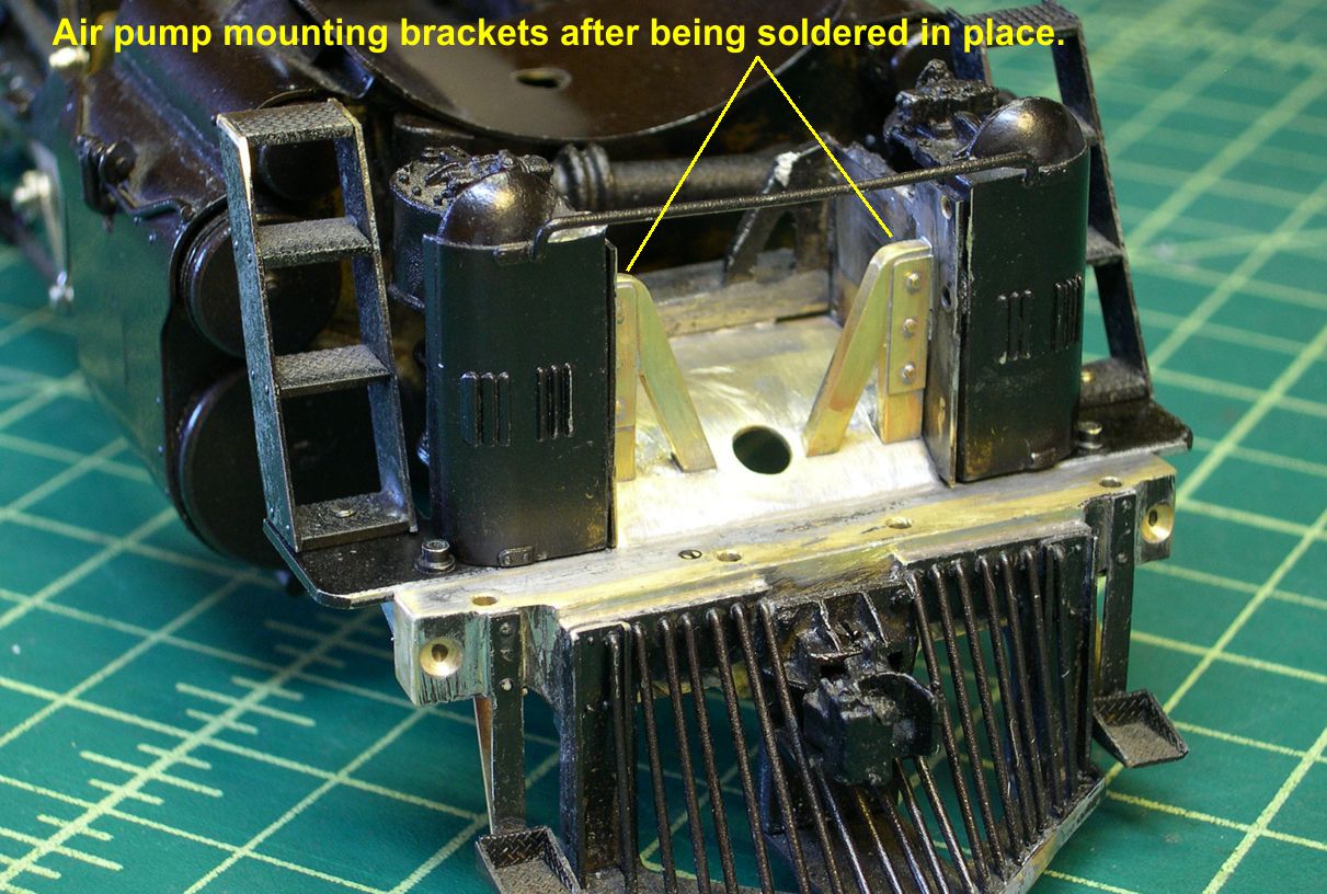
It is easy to see why they need to be so identical, as they sit right up front and beg for comparison. The small step on the bracket to the right in photo 37 was built up from 0.016″ thick brass edged with 0.010″ X 0.042″ brass strip.
photo 37 ⤵
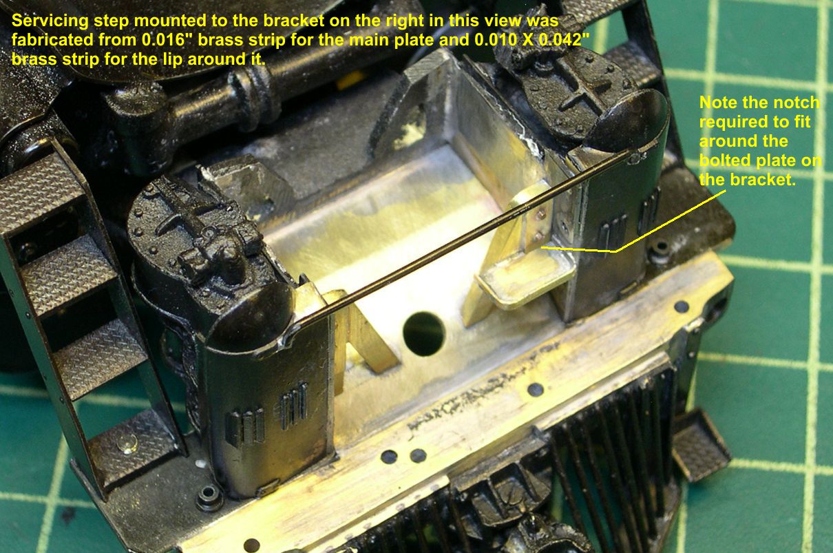
The 5011 class had such a step, but it was just a simple flat plate, no rim around it, so this one had to be scratchbuilt. Soldering that step in place was NOT an easy job. There is nothing to register it against and it has to be perfectly level. I wound up saying quite a few unprintable things while I was re-soldering, re-soldering, re-soldering, etc. (Twice!) Oh well, a couple of beers and I’ll be OK again. In the next installment, I’ll be plumbing up the air pumps, replacing the cut levers, and doing some miscellaneous detailing around the pilot.