AT&SF Class 5001 Tender 2
In this 33rd segment of the 5001 story, I finish the tender shell detailing. The first step was to fabricate the large tanks that go under the front deck of the tender. USH modeled only the ends of the tanks in order to allow room for a great huge connector right where the middle of the tanks would be. Since I will be using much smaller wire and connectors, I can model nearly the whole tank. Most ATSF tenders did not have this large tank under the front deck. It is an oil heater tank with steam coils inside and various connections for heating and piping the hot oil to the engine. As far as I can tell from the rest of the plumbing on the front end of the tender, the oil bunker itself was also heated. This oil heater tank must have been some kind of experiment for more controlled heating, but it was only used on the 20,000 gal square tenders. The later 24,500 gallon tenders did not have it, so I guess it was not worth the extra expense and complexity.
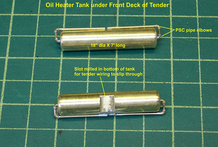
In photos 6 and 7, you can see the assembled oil heater tank assemblies.
tender 6 ⤵
tender 7 ⤵
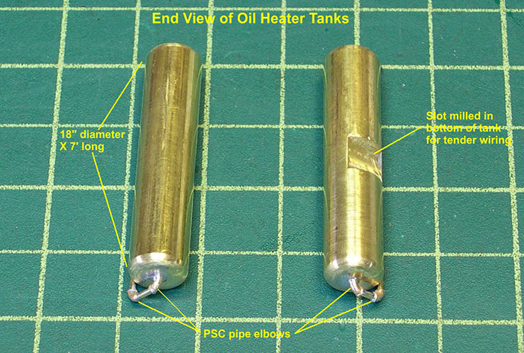
Since the diameter is 18″, 0.375″ scale, all I had to do was chuck up some 3/8″ brass rod in the lathe and use a file to shape the rounded end. Then I drilled a hole for the piping in the end, cut off the length at 7′, 1.75″ scale, and repeated the drilling and shaping on the second end. The piping was assembled using 0.040″ brass wire and PSC pipe elbow castings. I cannot model the full piping right in the center due to needing wiring back to the tender, but the wires and connector will somewhat simulate the oil piping to the engine. Visibility in that area will be very poor anyway, so I stubbed off the pipes and soldered them to the tanks for strength. I did have to mill a shallow notch in the bottom of the tank to clear the tender wiring, as you can see in the photos.
Photo 8 shows the piping on the front of the tender.
tender 8 ⤵
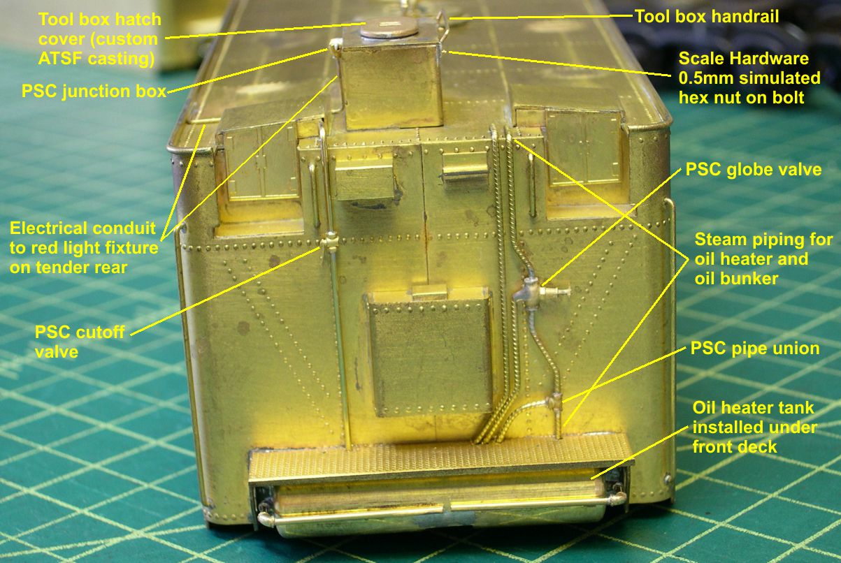
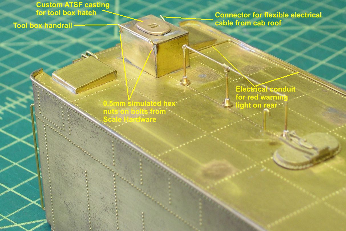
Due to the oil heater tank, it is somewhat more complex than usual. The large globe valve in the heater piping was modified with a hole in the bottom to make the type of valve the real thing had. The lagged pipe is PSC machined pipe. In photo 9, you can see the junction box on the side of the tool box.
tender 9 ⤵
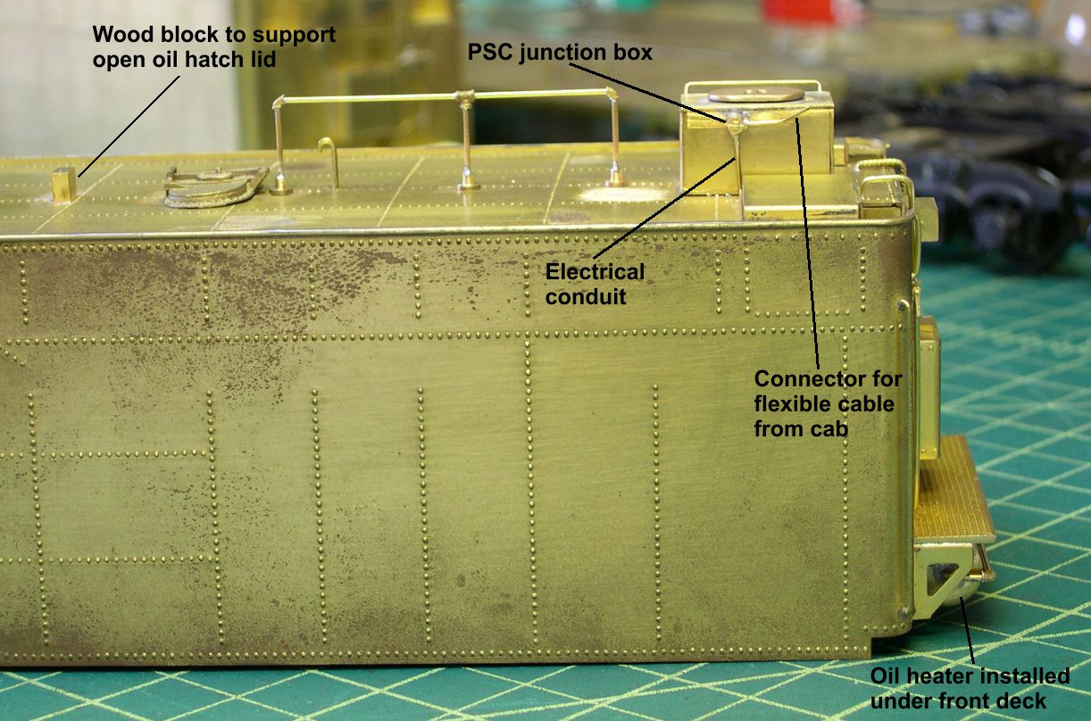
It provides a connection to the underside of the cab roof for the flexible electrical line between the engine and cab. The remaining photos show details I added all over the tender shell.
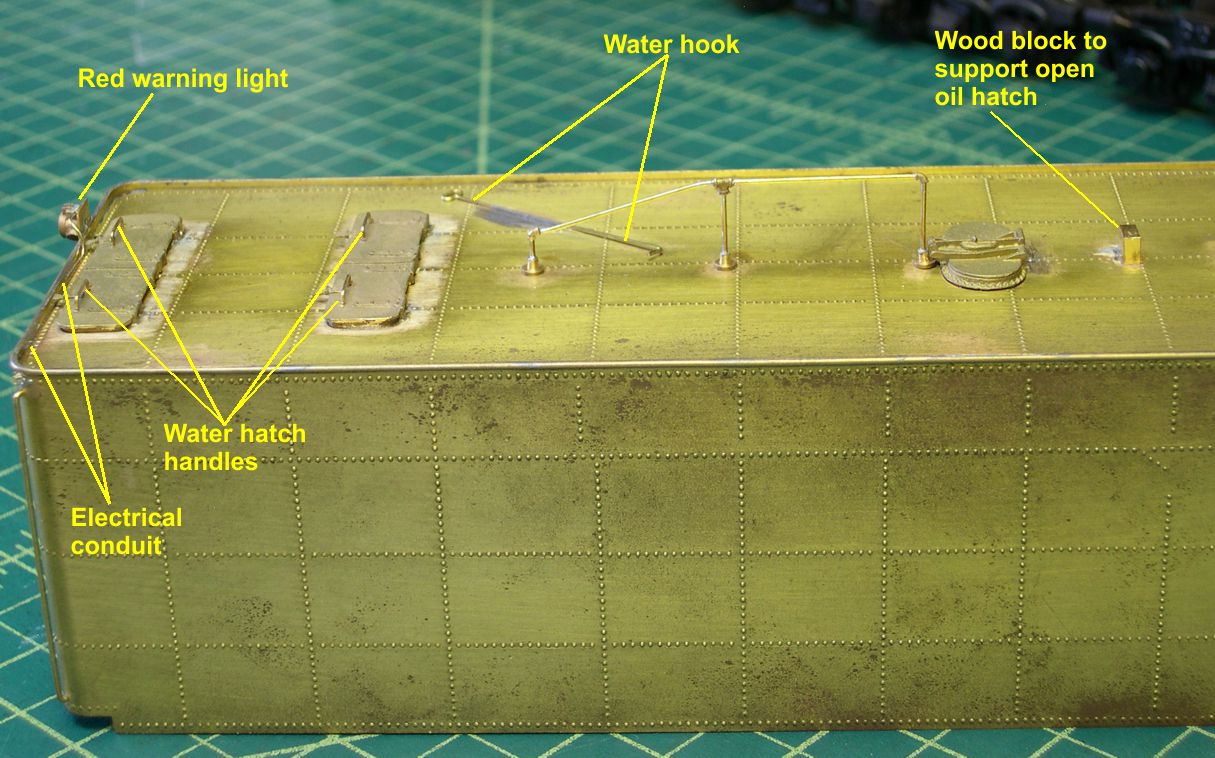
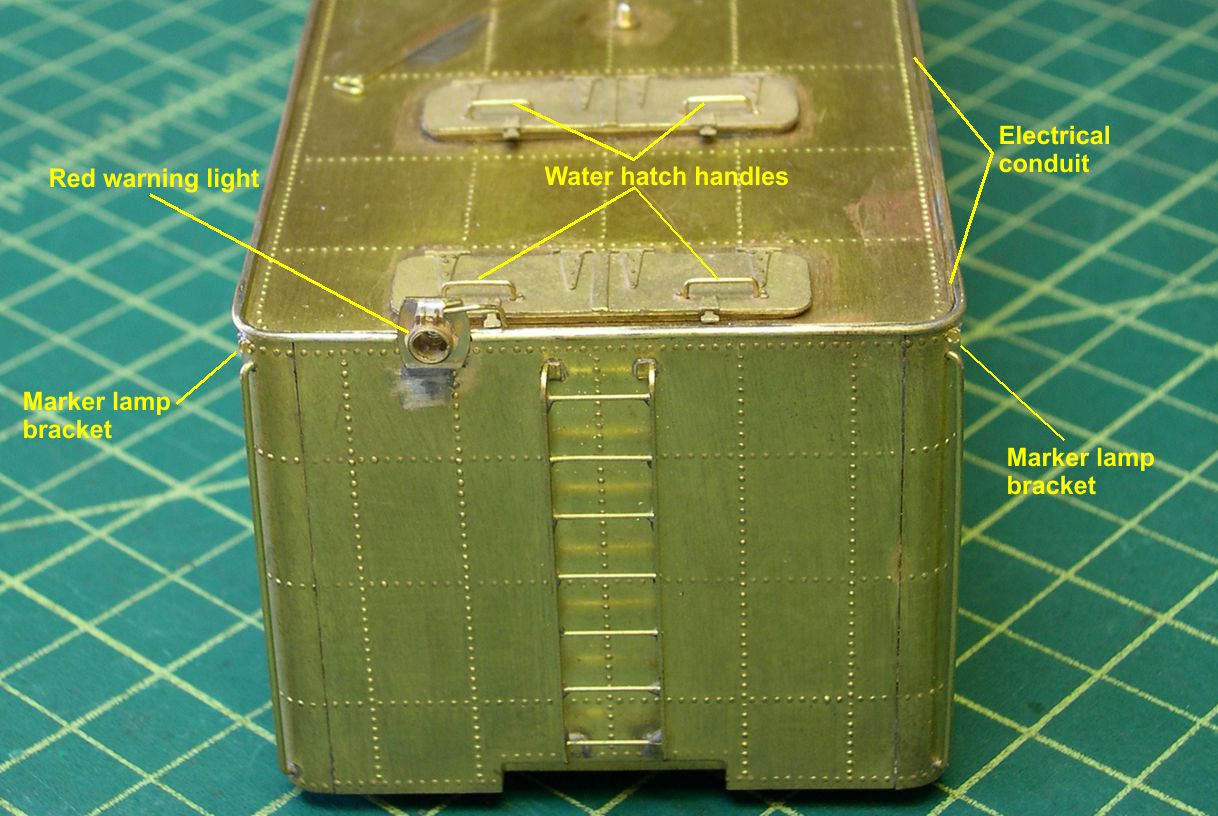
The water hatch castings have dimples cast into them for locating and drilling holes for the hatch handles. Next to the dimples are cast in nuts to simulate the ends of the handles bolted to the hatches. I have pointed out the handles in several photos.
tender 10⤵
atsf santa fe 5001 2-10-4 tender 11 ⤵
atsf santa fe 5001 2-10-4 tender 12 ⤵
tender 13 ⤵
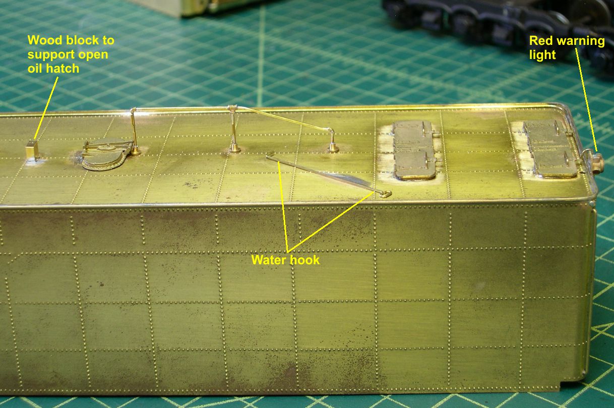
Notice that there is a single wooden block between the oil hatches positioned so that when either oil hatch is opened, the lid can rest on the wooden block. I generally just model the water hook lying on the top deck as that appears to be the norm in the photos I have studied. There actually are brackets provided for holding the water hook on the rear handrail uprights, as I have pointed out in photo 14.
tender 14 ⤵
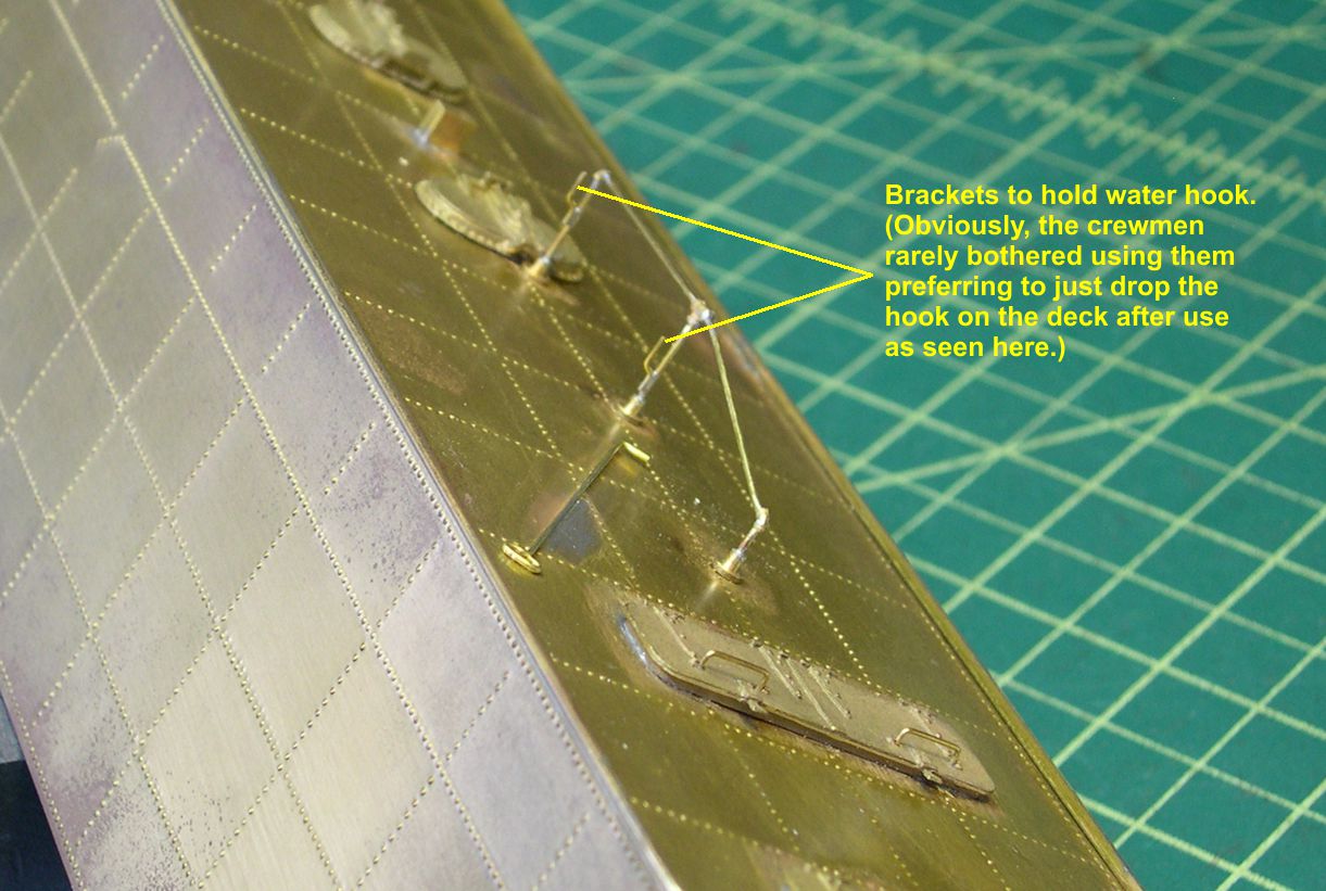
Guess most crewmen figured it was too much of a hassle to hang up the hook properly.
These 20K square tenders are the only ones I know of that use a slightly different mounting of the rear red warning light on the ATSF. My usual ATSF casting for the light has to be modified by cutting off the mounting bracket and soldering the light itself to a flat plate mounted on the end of the tender as shown in several of the photos. Now it is on to the frame and trucks.