AT&SF Class 5001 Misc Boiler Detail
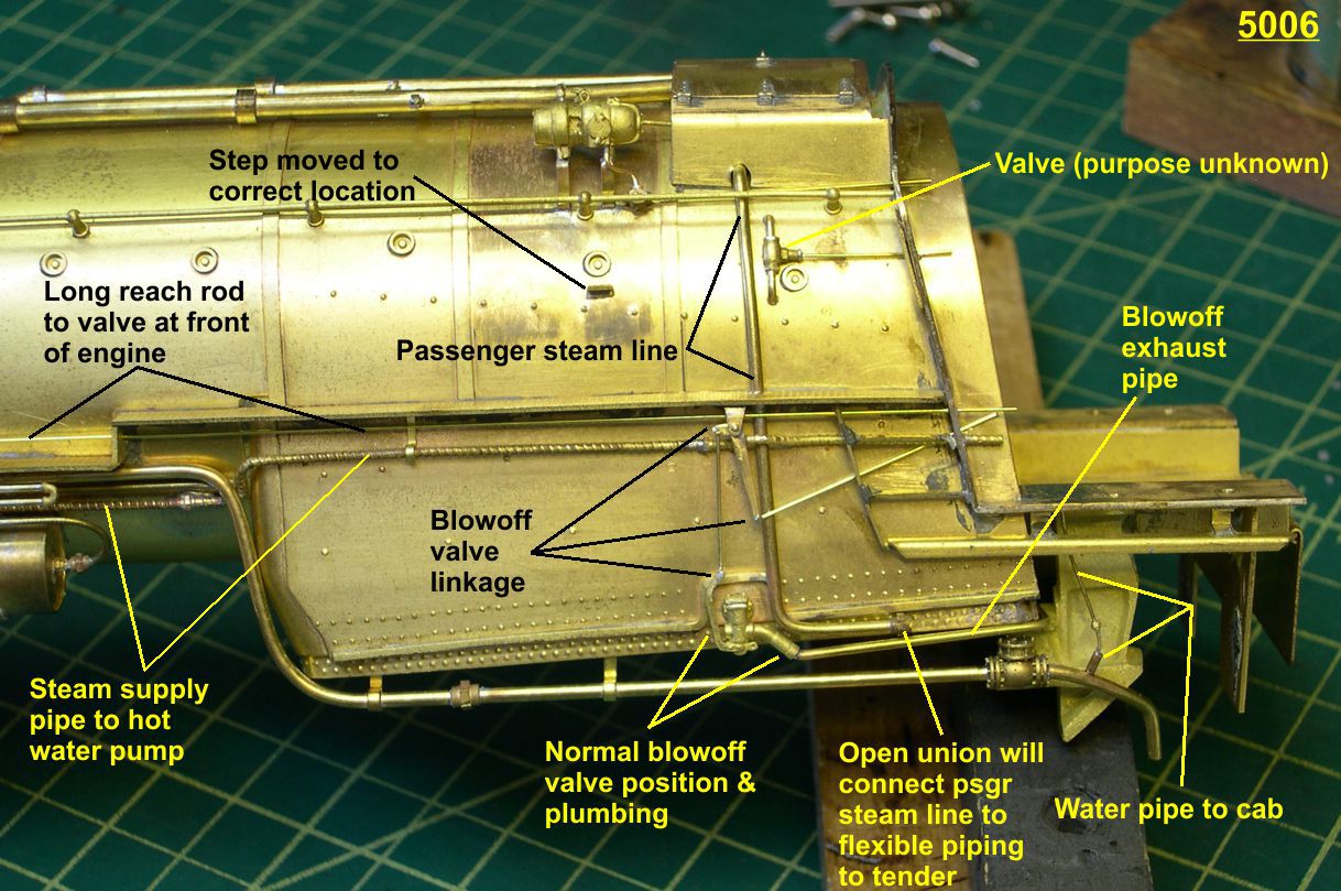
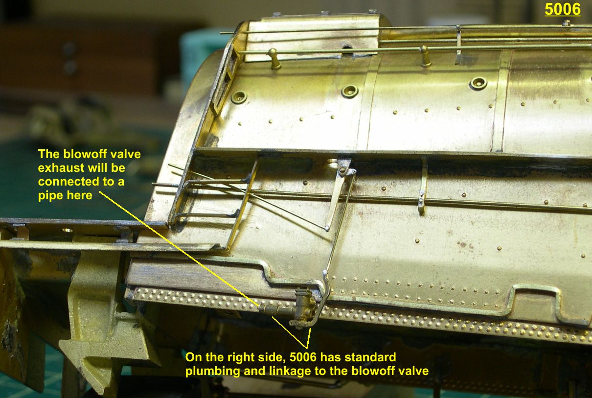
In this 20th installment of the 5001 class saga, I fill in a lot of miscellaneous details on the boiler, mostly the left side. There are quite a few differences in the detailing between engines 5006 and 5009. One of the most interesting differences is in the left side blowoff valve. Apparently, at some point in a shopping of 5009, someone could not come up with the correct left side blowoff valve, so they just installed a right side one and changed the blowoff exhaust plumbing to compensate. They also had to move the blowoff linkage closer to the cab to compensate for having the linkage on the wrong side of the valve. I have pointed out these differences in the photos. There are 12 photos attached, 6 from 5006 and 6 from 5009 to compare differences between them.
5006 1 ⤵
5009 2 ⤵
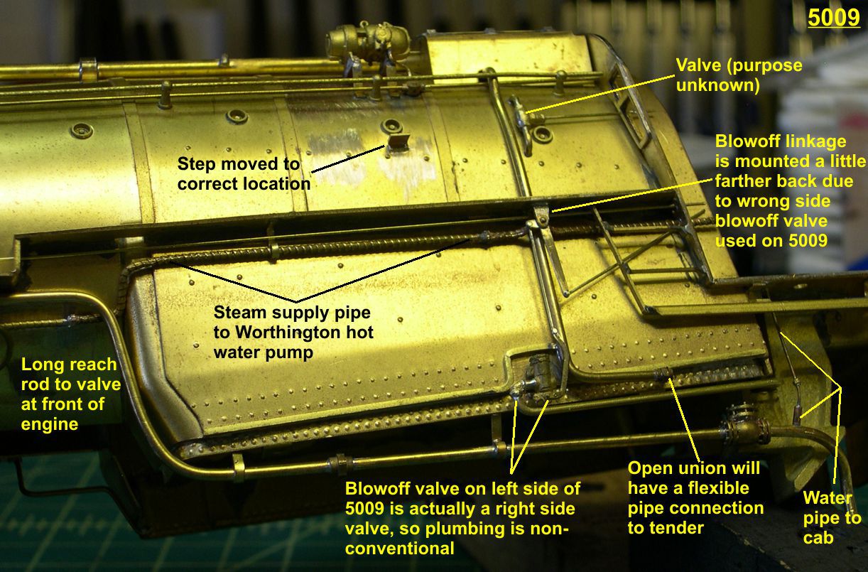
Many engines had a small pipe leading from the large cold water pipe from the tender up into the cab to supply water for hosing down the cab, etc. The 5001s were no exception. I installed the pipe by drilling a hole through the large cold water pipe and soldering a small pipe into it. After soldering I smoothed out the bottom part so it does not show. This gives a much stronger connection that will not break off. On the 5001 class, the small pipe was inserted into some larger connection with the large pipe, so I slipped a small piece of tubing over the small pipe to simulate that and added the pipe union used to disconnect the pipe for servicing.
5006 3 ⤵

5009 4 ⤵
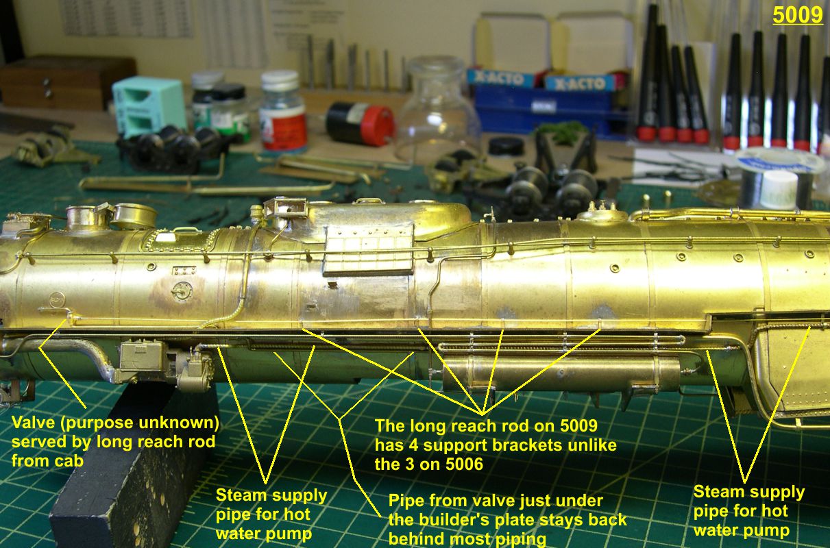
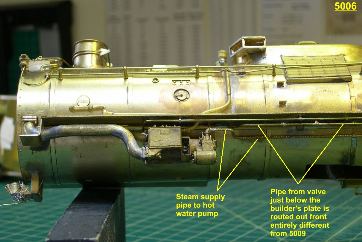
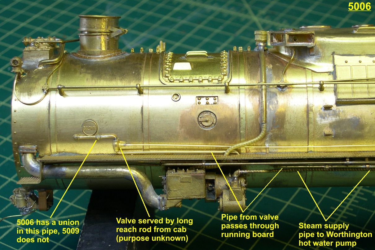
The live steam supply pipe for the Worthington hot water pump was added next. I used lagged pipe castings from Wiseman Model Services for this. They were originally Backshop castings, which are being reproduced by Wiseman. As you can see in the photos, this pipe runs from the hot water pump, back behind the cooling coils over the air tank, and back into the cab to the fireman’s controls.
5006 2 ⤵
5009 3 ⤵
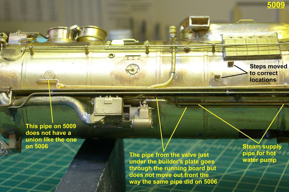
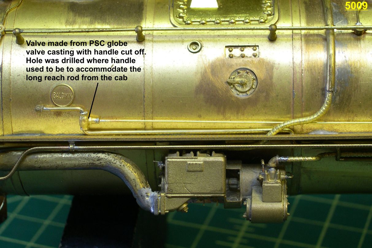
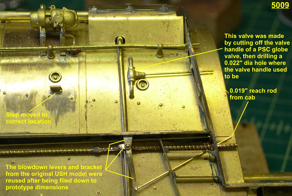
There are two valves, one on the smokebox and one just ahead of the cab, that I have no clue for their purpose. I made them from PSC globe valves with the handles cut off. Then I drilled a hole where the handle’s shaft used to be to accommodate the reach rods that activate them. The valve just below the builder’s plate on the smokebox is activated by a long reach rod from the cab. The number of brackets supporting this reach rod is another difference between the two engines. 5006 has 3 brackets, 5009 has 4. Also, the pipe from the smokebox to the valve has a pipe union in it on 5006, but none on 5009. Thirdly, the pipe leading back toward the rear of the engine from that valve takes different routes. On 5006, it passes through the running board then moves out front just behind the cooling coils as it goes to the rear. On 5009, it also goes through the running board but then stays back along the boiler amongst other piping and is lost behind the cooling coils.
5006 5 ⤵

5009 6 ⤵
The small steps on the sides of the boiler are differently placed between the two engines and certainly different than on the USH model originally. The step under the generator is farther back and higher than the original. The two steps under the sand dome are in a straight line vertically on 5006, but staggered on 5009. All these steps had to be unsoldered and moved to their correct locations as shown in the photos.
5006 4 ⤵
5009 5 ⤵
I had to do the large passenger steam line prior to some of the other stuff since other pipes go over it. The passenger steam line is the pipe that drops vertically from the turret ahead of the cab to the bottom of the firebox then turns toward the rear of the engine. I left an open union on it where the real thing had a union. I will use that union to hook up the passenger steam line through flexible piping to the tender. It takes three u-joints to complete that line.
5006 6 ⤵
5009 1 ⤵
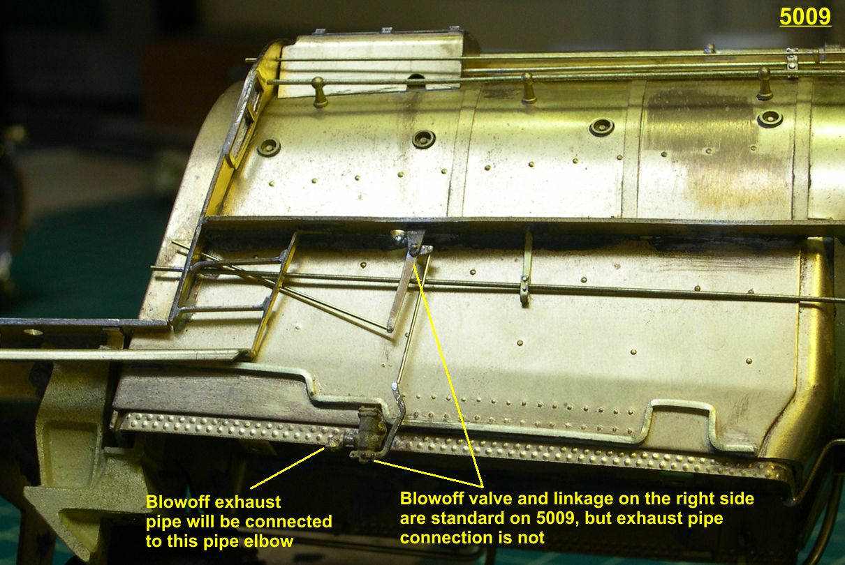
Finally, I installed the blowoff valves on the bottom edges of the firebox. There is a right and left to these valves, as the linkage normally connects to the front of the valve and the exhaust pipe exits the rear. However, as noted in the first paragraph, at some point 5009 got a right side valve installed on its left side causing the linkage and exhaust pipe to both be modified to accommodate it. For some reason, both blowoff valves on 5009 used a pipe elbow on the exhaust pipe, while 5006 used a longer standard fitting to connect up the exhaust pipe. These differences have been pointed out in the photos. The linkage levers and bracket from the original model were basically correct but too fat. I filed them down to size and reused them.
Only a couple of minor things remain to be done on the left side of the boiler now, then I will start in on the right side where I still need to do the injector and all its connections.
Gary
Adendum
Gents,
One advantage of publishing your work is that you get valuable feedback from time to time. A good case in point is the “unknown purpose” valves I installed in part 20 of this saga. Ray Grosser wrote to inform me that the valve just in front of the cab was almost certainly the fireman’s blower valve, as that is a common location for them. Sounded logical to me, so I went back to the video I shot of ATSF 5030 in Santa Fe, NM, a few years ago. While not a 5001 class, the main plumbing and details are nearly identical, so this is a valuable video for researching details on the 2-10-4 engines, especially since 5030 had its lagging removed revealing a lot of plumbing connections and routing one could not normally see. I video’d 5030 from all sorts of angles and zoomed in on all the details, knowing I would need the info one day.
Well my research on the video proved that Ray is exactly right. The pipe that valve is on goes from the turret ahead of the cab, under the lagging, and up towards the front of the engine. In fact, it is the same pipe that the valve on the smokebox is on, and that pipe goes into the smokebox exactly where it should in order to be the blower pipe. I confirmed that from some drawings and info in various Loco Cycs. So both of those valves are actually the fireman’s blower valves. That leaves me with one question that someone might know: Why are there two valves for the same function, one back at the cab and one just outside the smokebox? There is no connection to the pipe between the two valves, just a solid pipe. Did they need a backup in case of one valve malfunctioning? Or did the distance cause a slightly different effect when using one valve vs the other?
At least we know what the valves do now, so they are no longer “purpose unknown”. Thanks, Ray.