AT&SF Class 5001 Continuous Blowdown Valves
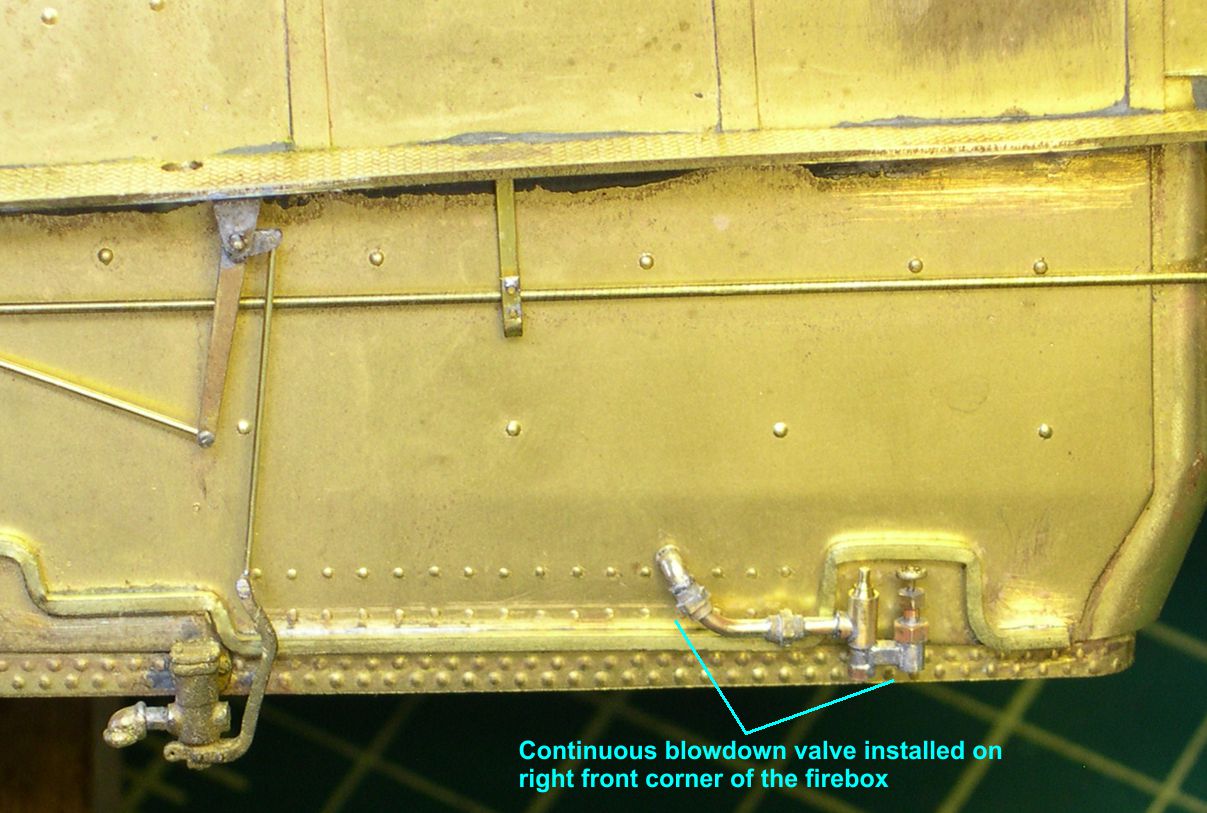
This installment consists mainly of scratch building 4 continuous blowdown valves for these engines. Unfortunately, no one makes a casting for these valves, and I couldn’t find any casting close enough to modify, so I had to start from scratch. A continuous blowdown valve is used, as the name implies, to create a continuous blowdown effect on the mud ring of the firebox. I first identified this type of valve while doing the detailing work on the SP AC’s. SP had installed a single continuous blowdown valve on the left front corner of the AC fireboxes (equivalent to the right rear of a conventional engine). This was a recommended location according to the Loco Cyc. Apparently, the SP was a little under whelmed by the device, and they were removed about the same time the Locomotive Pilot devices were removed around 1950 or so. The ATSF obviously had better feelings about them, as they installed two in the fireboxes of the later engines, rather than just one. The ATSF had particularly bad water in the Southwest, so maybe the benefit was greater for them. At any rate, the big Northern and Texas types kept them to the end. They had one on the left rear corner and one on the right front corner.
I had to take a photo on one of these valves off my TV using the video of ATSF 5030 I took in Santa Fe, NM. I then calculated the dimensions off the photo using the opening in the lagging as a reference dimension. I then broke the valve down into a series of parts that I could fabricate and solder together for the final assembly. The 11 photos attached show visually how I did this. There are several hex nut shaped parts to the valve, so I used a couple different sized hex nuts for those parts. By pinning the parts together, as shown in the photos, you get a much more solid assembly that is not so prone to damage if bumped.
photo 1 ⤵

photo 2 ⤵

photo 3 ⤵

photo 4 ⤵
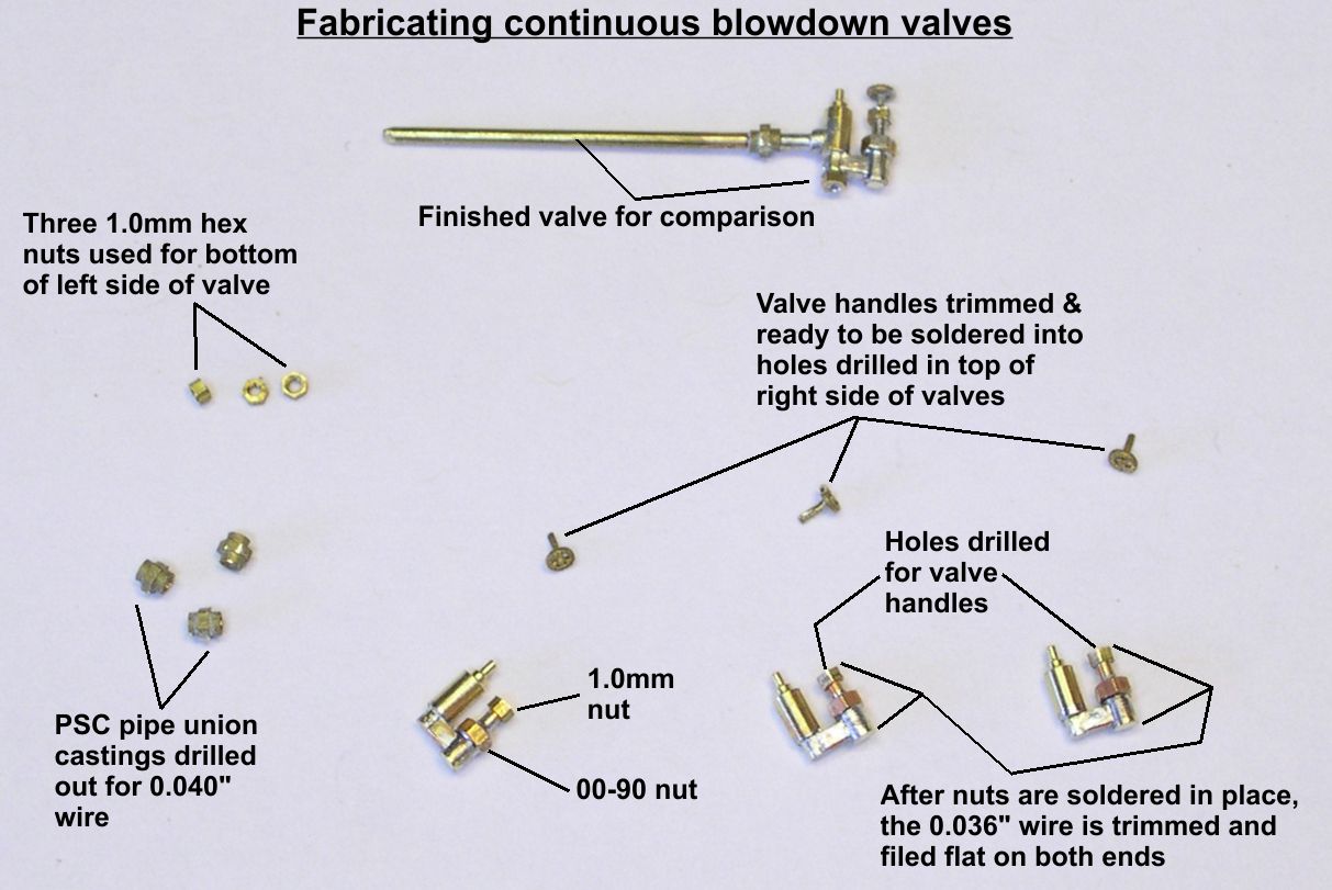
photo 5 ⤵
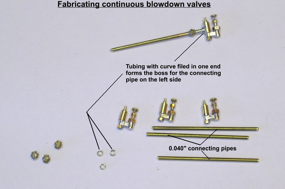
photo 6 ⤵

photo 7 ⤵
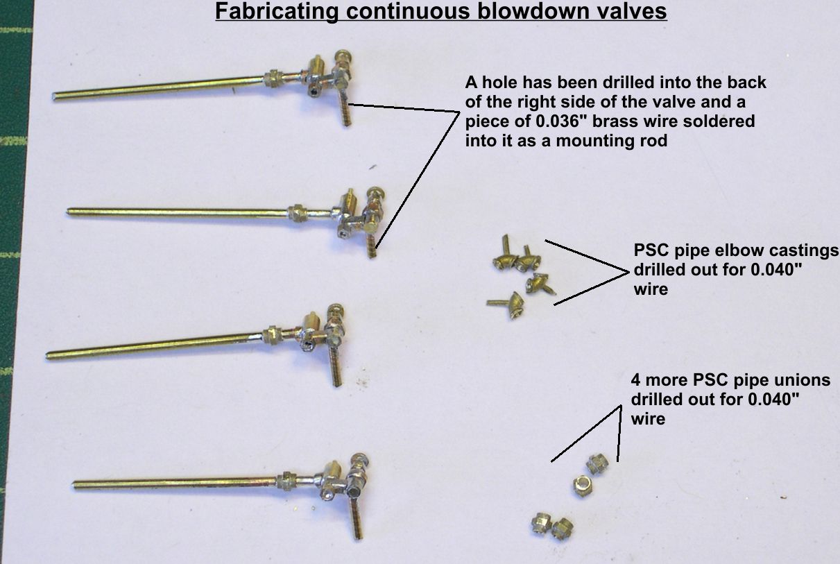
photo 8 ⤵
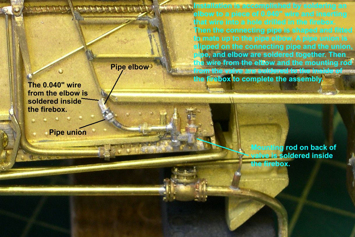
photo 9 ⤵
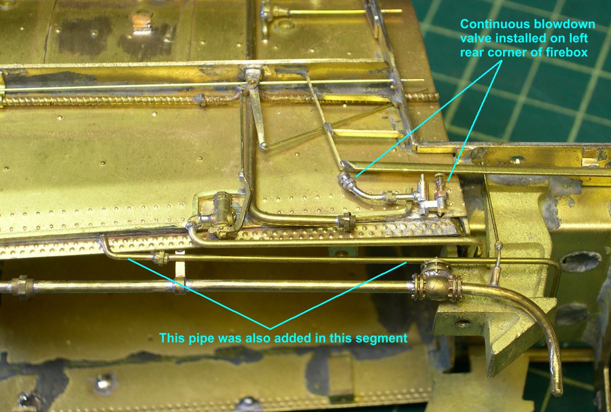
photo 10 ⤵
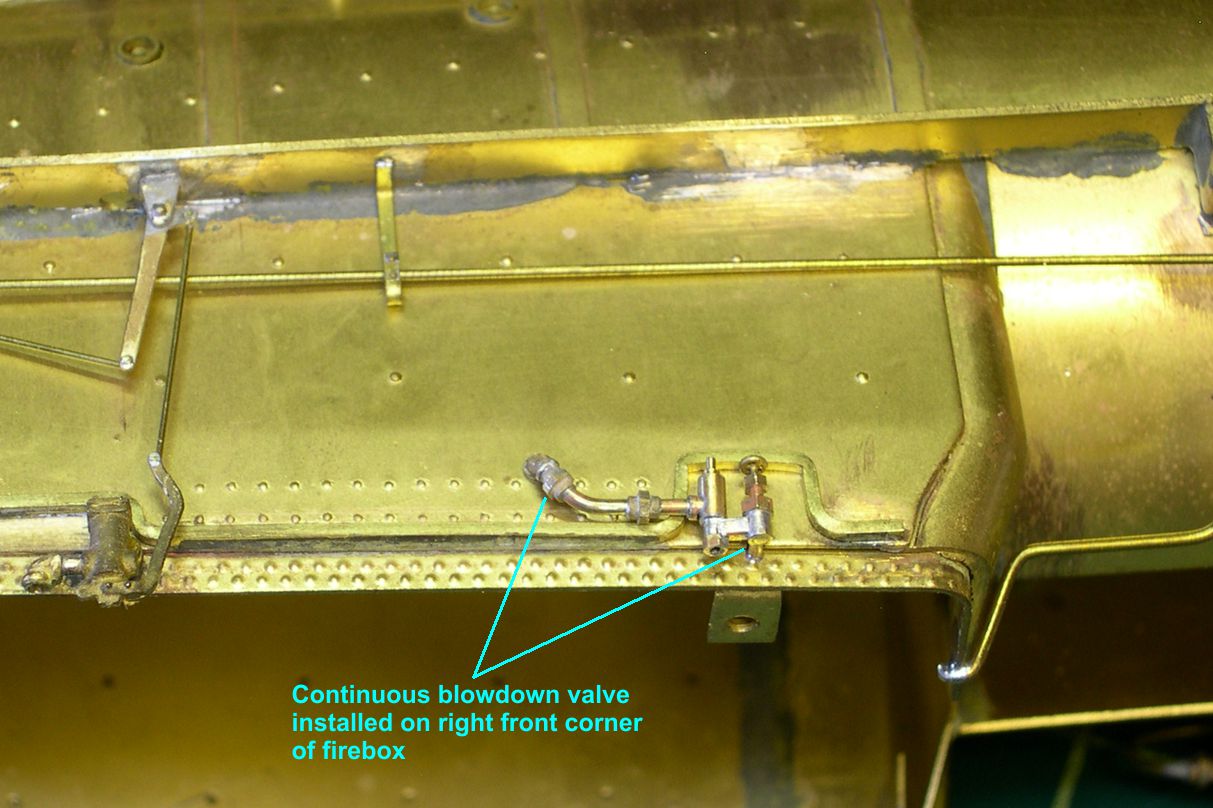
photo 11 ⤵
While tedious and finicky to make, these continuous blowdown valves are pretty obvious on the engines, so I could not just ignore them. I also added another pipe on the left side of the firebox. I do not know the purpose of this pipe, but both engines had it. It comes out from under the lagging at the bottom of the firebox, runs horizontally back toward the rear, and disappears under the cab.
FYI: For those who have been wanting the ultimate Big Boy, Key has announced it. It will be done by the same builder, to the same standards, as the SP ACs. See Key’s website or your dealer to get more details. Reserve early, as there will not be extras sitting around waiting for you.
Since I have to get acquainted with the Big Boy in order to direct its construction, I have spent a little time looking at photos, etc. Interestingly enough, the Big Boy used exactly the same arrangement of blower valves as these ATSF 2-10-4s did – one just in front of the cab and one right where the blower pipe enters the smokebox, with a very long reach rod from the cab to that front valve. This proves that the front/rear arrangement of blower valves was not haphazard. There is some important reason to have 2 valves on the same line. Maybe it was some method of handling condensation or freezing on this long pipe during intermittent use of the blower?