AT&SF Class 5001 Boiler Top
At the end of part 12 of this saga, the logical next step was to plumb up the air pipes to the new air tanks. That is what I intended to do. However, in trying to figure out exactly how the air pipe from one side of the boiler to the other ran in between the sand dome and the steam dome, I suddenly realized I had a BIG problem. Namely, the prototype had NO steam dome in this timeframe. This is a perfect example of how we all see what we expect to see, not necessarily what’s really there. How many of you noticed the missing steam dome on the prototype photos of 5006 and 5009 I sent out earlier? Be honest now . . .
I was surprised by the missing steam dome, but not shocked. I knew the ATSF had applied boilers of that type to a number of 4-8-4’s. I just didn’t know they also did it to the 5001 class. Here’s the story. In the 1937-38 period, Santa Fe started building their super power steam engines, the 3765 class 4-8-4, the 3460 class 4-6-4, and the 5001 class 2-10-4. A bit later, pre-war, they also built the 3776 class 4-8-4. All these super engines got nickel steel boilers. During WWII, nickel steel was not available, so the 2900 4-8-4 and 5011 2-10-4 built during the war had to settle for carbon steel boilers. Turns out that was a blessing in disguise. As time passed, the nickel steel boilers began to crack and leak, so the ATSF had to replace them with carbon steel boilers. Around 1948, the Santa Fe (or someone at any rate) developed a new type boiler with no external steam dome. It had some sort of internal steam collection system. I personally do not know how it worked. Maybe someone out there does? At any rate, several of the 3765 and 3776 class Northerns received new domeless boilers by 1950. In reviewing photos in the light of my new discovery, I found that 5001 through 5009 definitely got new domeless boilers around 1948. I do not have a late enough photo of 5010 to be certain about it, but I imagine it also was so equipped. If anyone happens to have a photo of 5010 from 1949 or later, I would love to see a scan of it. By the way, the boiler change coincides with the change to the duplex, top mounted check valves. Prior to that, the check valves had been moved up from the sides of the boiler to a location high on the boiler, but not at the very top. One source says only 6 of the 10 engines got new carbon steel boilers, but I am skeptical that the Santa Fe would have gone to the trouble of rebuilding the old troublesome nickel steel ones with new innards and new check valve locations. I would bet that all members of the class got new carbon steel boilers with top mounted checks and inside steam collection, with the possible exception of 5010, of course, since I have no photographic evidence on that one. (Sorry for going on and on with this prototype info, but I know the ATSF fans out there will be fascinated with it. Now back to modeling.)
The routing of the distinctive twin outside dry pipes on domeless boilers was different. As built, the outside dry pipes ran from the steam dome, jogged around the pop valve cluster, and went back into the turret ahead of the cab. For the domeless boiler, the outside dry pipes exit the boiler just behind the pop valve cluster and run back to the turret ahead of the cab. Obviously, I would have to make significant changes to the model to correctly model the domeless boiler. I started by using the heat gun to remove the steam dome and dry pipes. I decided to remove the old generator and the clunky casting for the turret hatches as well. See photo 1 for how the model looked after all the removals.
photo 1 ⤵
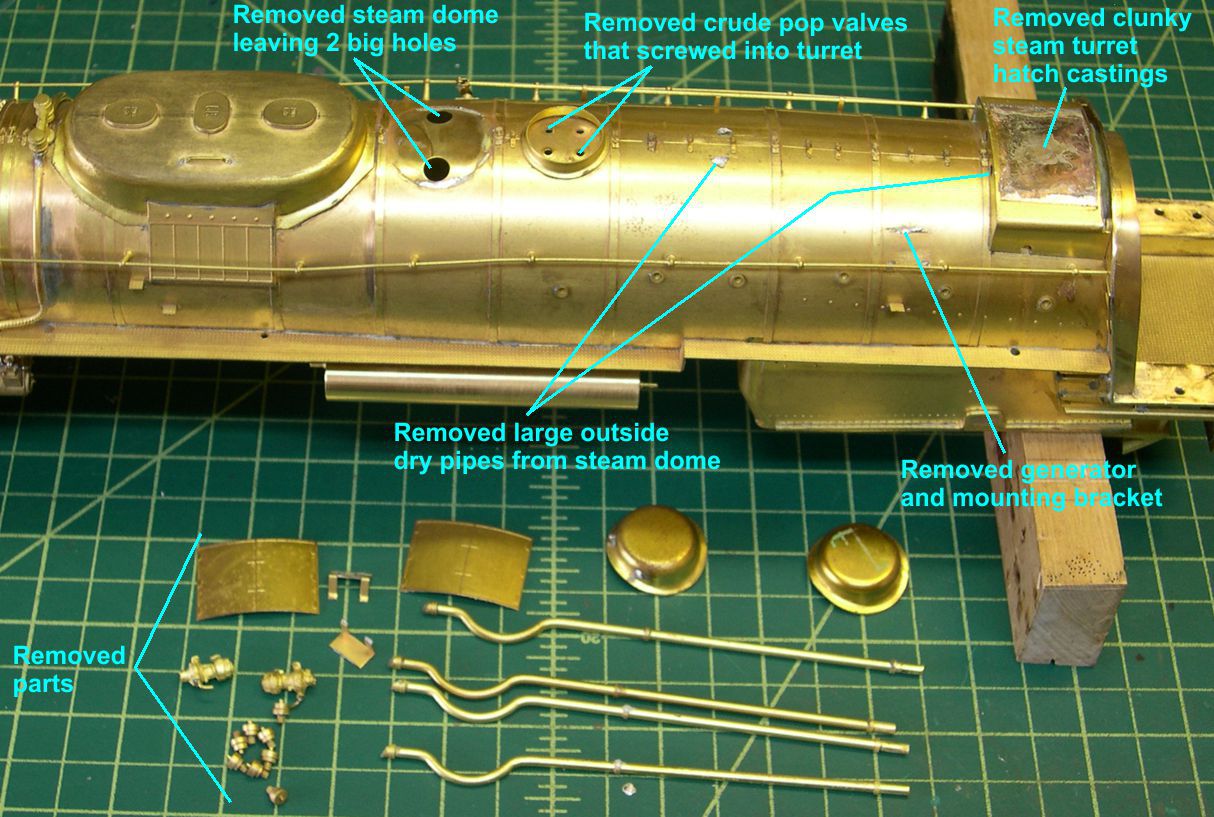
Notice that there are two big holes in the boiler where the steam dome was. Drat! Apparently, USH had intended to solder the steam dome in place from underneath, but they actually soldered it from the top. Of course, they did not eliminate the holes, so I had to.
To plug the large holes, I used my usual technique of making special turnings to plug the holes. The top of the turning was 0.026″ high and just barely able to fit into the hole. The bottom was 0.040″ greater in diameter and 0.010″ thick to form a flange to hold the plug in place from below. Due to the curve of the boiler, I had to bend the plugs slightly so they fit better. After soldering the plugs in place, I filed and sanded them down to fit the rest of the boiler. See photo 2 for the appearance of the area under the dome following the plugging.
photo 2 ⤵
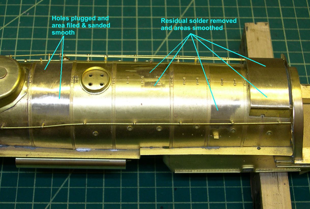 The rest of the solder residues have been cleaned up as well.
I studied the photos of 5006 and 5009 carefully to determine exactly how the outside dry pipes ran. I was pleased to discover that the two are not identical. I have been looking for differences between the two engines, so I could easily tell them apart. So far, the only thing I had found was a difference in the location of the air reservoir tank under the cab for the Westinghouse distributing valve. That’s kind of subtle though. The dry pipe routing on 5006 was straight forward enough. it just goes straight back from behind the pop valve cluster and turns inward just before entering the steam turret ahead of the cab. At first, I couldn’t figure out what the pipes on 5009 were doing, as they seemed to be misaligned just back of the pop valve cluster. It finally dawned on me that it looked that way because they angled back toward the center just after exiting the boiler, then ran straight back into the turret. That means the dry pipes on 5009 are much closer together along the top of the boiler than are the ones on 5006. That’s a nice easy difference to see between the two engines.
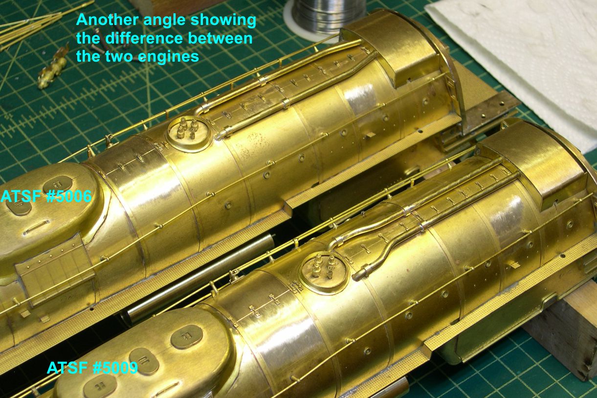
Photos 3 and 4 show the tops of the two engines after I fitted up the new outside dry pipes and added lagging clamps to the newly bare area where the steam dome used to be.
photo 3 ⤵
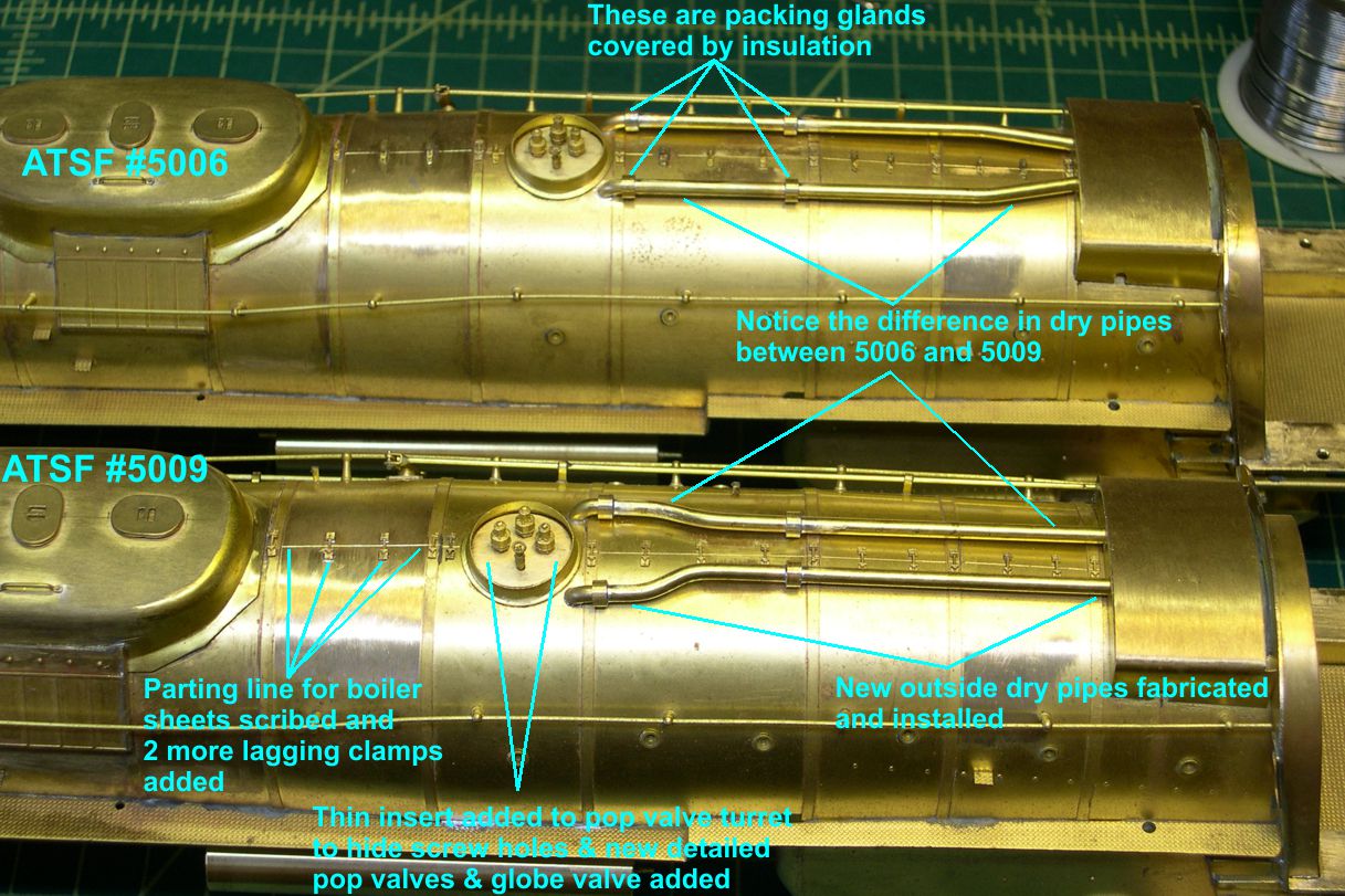
photo 4 ⤵
As mentioned earlier in this series, I use a sharp steel scribe to scribe a parting line into the boiler where the cover sheets join before soldering in the lagging clamps. The two large rings on the dry pipes represent insulation covered steam glands where the sections of pipe join. They are turned on the lathe to fit exactly.
The holes for the pop valves in the pop valve cluster were in the wrong places. They had to be rotated 45 degrees. Rather than do a bunch of plugging and smoothing within the confines of that round ring, I just turned a couple of very thin, 0.015-0.020″ thick discs to cover the bottom of the cluster. After bending the discs to fit the curvature of the boiler, I soldered them in place, drilled new holes in the right locations, and soldered in the new pop valves and globe valve. The original model had 4 pop valves – obviously not correct. I could not locate any photos that were totally definitive on the arrangement of the pop valve cluster. In some cases, it looks as if there are only 2 pops and a globe valve. However, from the obvious locations in the cluster from different angles, I finally decided on 3 pops and one globe valve in the arrangement shown. Hopefully that is correct.