AT&SF Class 5001 Cab Lights – Weight – Number Boards – QSI Wiring – Window Glass
This episode takes care of a bunch of odds and ends that have to be addressed before “completeness” is achieved. There are 16 photos attached to help you follow along. First item on the agenda is a new boiler weight. See photo “New Weight”.
new weight ⤵
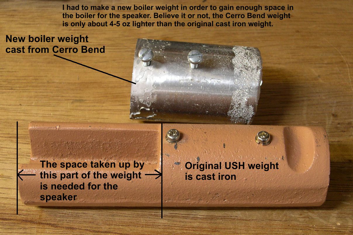
Unfortunately, the original USH weight is really long and uses up the space I need for mounting a speaker in the boiler, so it had to go. Casting a new weight out of Cerro Bend is really easy, as Cerro Bend melts slightly below the temperature of boiling water. I just make a tube out of shim brass and pour the melted Cerro Bend into it and let it harden. The original USH boiler weight is made of cast iron, which has a significantly lower density than low temperature Cerro Bend, which is closer to lead in density. Consequently, the much smaller new weight weighs nearly the same as the original USH weight. It is only 4-5 oz lighter, which is hardly noticeable in such a heavy engine. The new weight frees up the area just ahead of the mechanism, where the boiler becomes completely round again, for the speaker. I used a 1.77″ diameter high bass speaker sealed into the boiler with double sided mounting tape. I have pointed out where it is in the photo “QSI Wiring”.
QSI wiring ⤵

You can’t actually see the speaker, as it is black, but you can see the gray mounting tape sealing it into the boiler.
While we are on the photo “QSI Wiring”, I may as well cover the decoder. I used a QSI Titan 6-10 amp Large Scale sound and DCC decoder. It is slightly more expensive than the two decoders I use when I install a Tsunami. However, it has some nice features I wanted for these models. First of all, due to the way QSI synchronizes the chuff to BEMF on the motor, no sound cam is needed. That is a significant time savings and worth the extra cost to me. The sound files are really great on the QSI, and they have actual Santa Fe whistles – another big plus. I can also get 2-3 more lighting controls if I so desire, so I will be making the light on the back of the cab roof, the red warning light on the rear of the tender, the cab lights, and the class lights all operate independently. With a Tsunami set up, I would have to combine some of these. This is not a huge item, but it’s kind of fun. In the photo, I have shown the hook ups to the QSI. However, that is far from the whole story, as I have rearranged ports and assigned functions to fit what I want. You cannot do that without a programmer, and no way am I going to go into the necessary dissertation here. Just suffice it to say that there is a huge learning curve to working with QSI decoders. Whether or not it is worth it to you is your decision. The photo is more for my use than yours. With it, I can remember how to wire the second engine without having to reinvent the wheel.
Here are the functions performed by the keys on the DCC controller the way I have chosen to set up this QSI:
- F0 – Headlight & number boards
- F1 – Bell
- F2 – Whistle
- F3 – Arms the cylinder cocks when stopped, Flange squeal when moving
- F4 – Red warning light on rear of tender
- F5 – Cab lights
- F6 – Class lights
- F7 – Light on back of cab roof
- F8 – Mutes all sounds
- F9 – Long air release when stopped, Air brakes when moving
- F10 – Coupler sounds
- F11 – Water filling sequence when stopped, Speed announcement when moving
- F12 – Injector sounds when stopped, Chooses between whistles when moving
There are a lot of ways to customize a QSI. These are just my personal preferences. Even though the decoder is quite large, it fits neatly in the top of the boiler just over the drive train as indicated in the photo. There would actually be room for more weight in the boiler if one wanted more, but I can hardly lift this monster anyway. Why would I want any more?
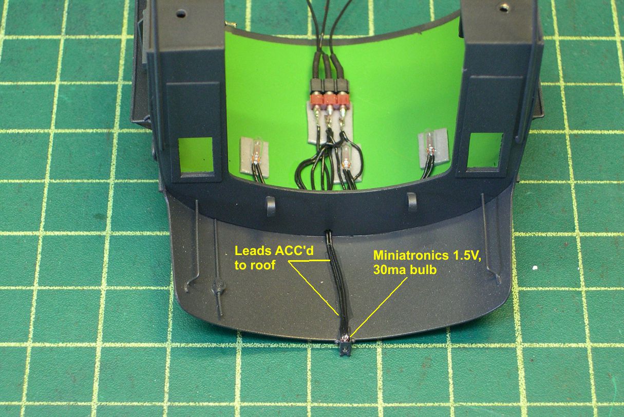
The photos “Cab Lites-1,2,3” show how I installed 3 large bulbs in the cab ceiling to illuminate the cab interior and make it possible to view all that backhead detail.
cab lights 1 ⤵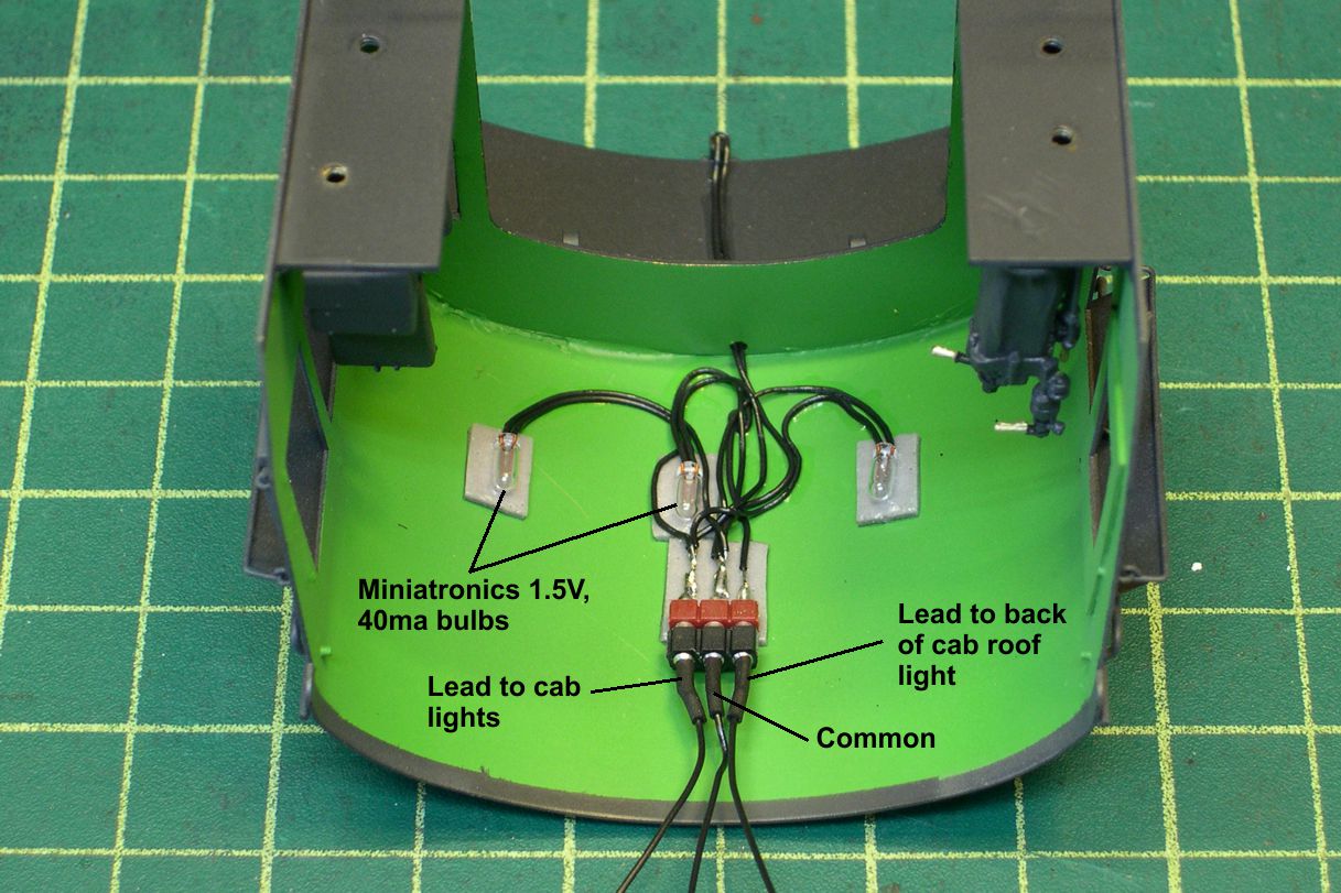
cab lights 2 ⤵
cab lights 3 ⤵
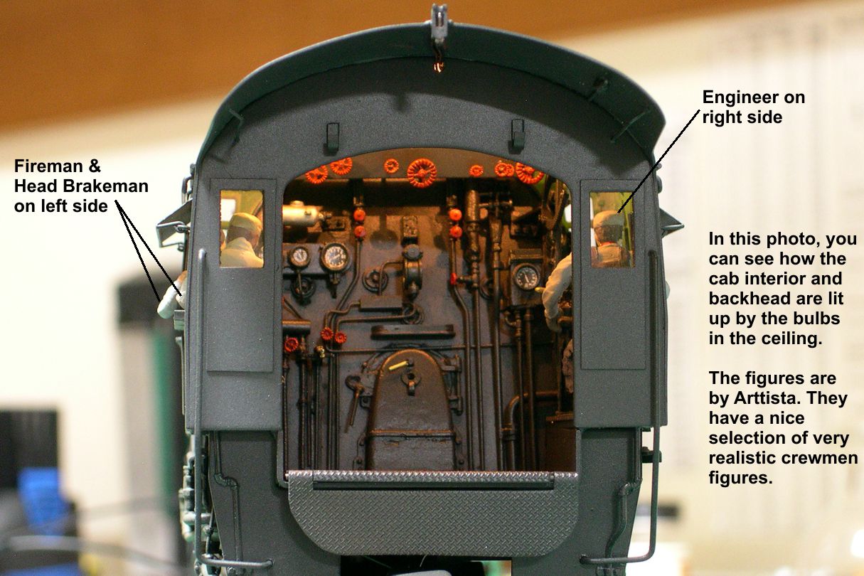
In the same photos, I show how the light on the rear of the cab roof is wired up as well. For non-Santa Fe modelers, all ATSF steamers had this light fixture mounted there to light the top of the tender at night for the fireman. FYI: In a darkened room, that light really does light up the top of the tender very nicely. The 3rd photo shows how the backhead is lighted when the cab lights are turned on. I took that photo after I had installed the window glass and cab crew, then reinstalled the cab on the boiler.
Speaking of window glass, it’s time to discuss how I install real glass in all my windows. It’s really pretty easy once you get used to it. The real secret to successfully using real glass is to get yourself a good quality diamond scribe. For some time, I tried to use a cheaper carbide scribe, but I broke enough glass to easily pay for a diamond scribe. Once I got a decent diamond scribe, I found I could cut glass almost as precisely as styrene or other materials. There is very little breakage with a diamond scribe, and I can trim as little as 0.030″ off a piece of glass, perhaps a little less. A second secret is to use transfer adhesive instead of glue for attaching the glass. In the photo “Window Glass-2”, I show the transfer adhesive I have used for years now.
window glass 2 ⤵
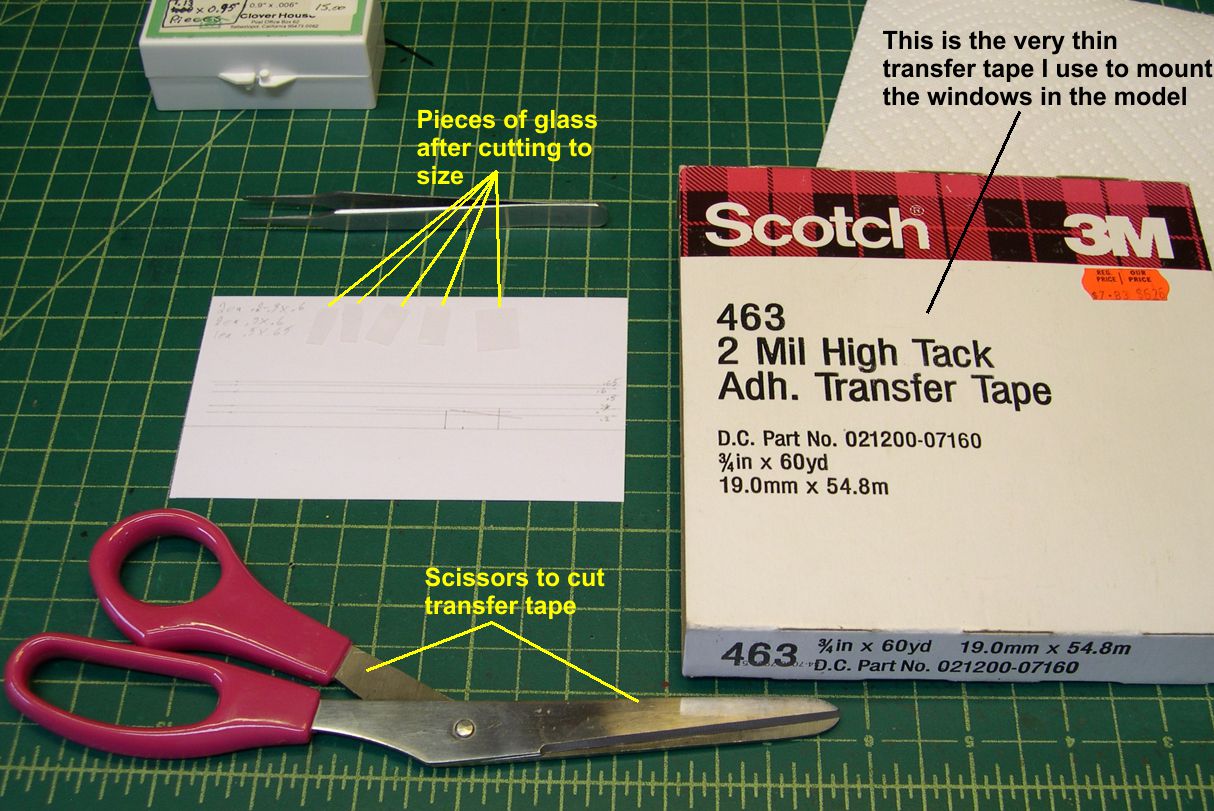
It is very thin and very strong. Once in place, you pretty much have to break the glass to remove it. The adhesive just does not let go, even after decades. It is also transparent, so it does not show much at all. It will also not squeeze out into the window space as glues often do. As you can see in the photos, you just cut a small piece and stick it on either side of a window opening, remove the paper backing, and then press the glass into it. Couldn’t be much easier or more permanent.
In the photo “Window Glass-1”, I show the 3X5 card I draw lines on for scribing the glass.
window glass 1 ⤵
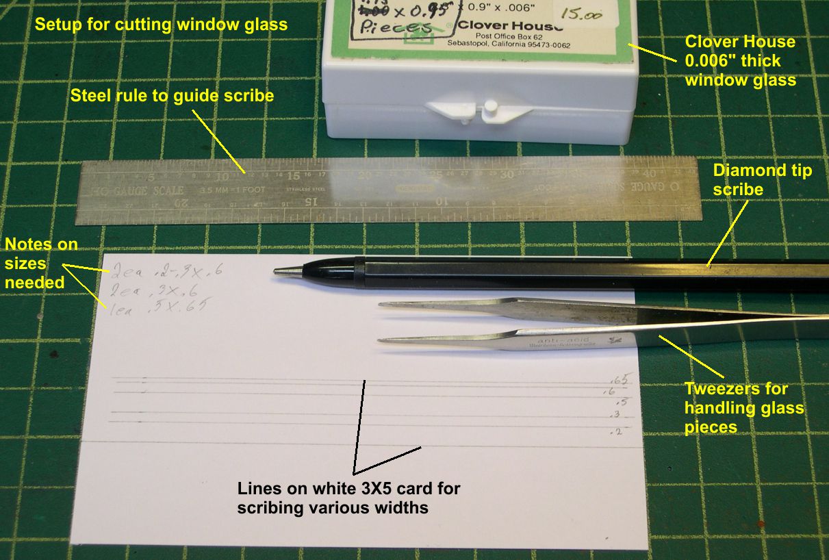
I determine the dimensions needed for all the windows, then draw a line for each dimension. The piece of glass is placed against a steel ruler that has been positioned along the bottom line. Then the ruler is moved up over the appropriate line for cutting and the scribe is drawn along the ruler to scribe the glass. When you pick up the glass with tweezers and try to bend it along the scribe line, it will snap off right along the line. In the photo “Window Glass-2”, you can see the various pieces of glass I cut for the windows in the cab of this engine; the two front windows, the two rear windows, and the single side window on the engineer’s side that is not open. In photo 3, you can see the roll of adhesive transfer tape and some pieces that have been cut and placed on the top and bottom of the front windows.
window glass 3 ⤵
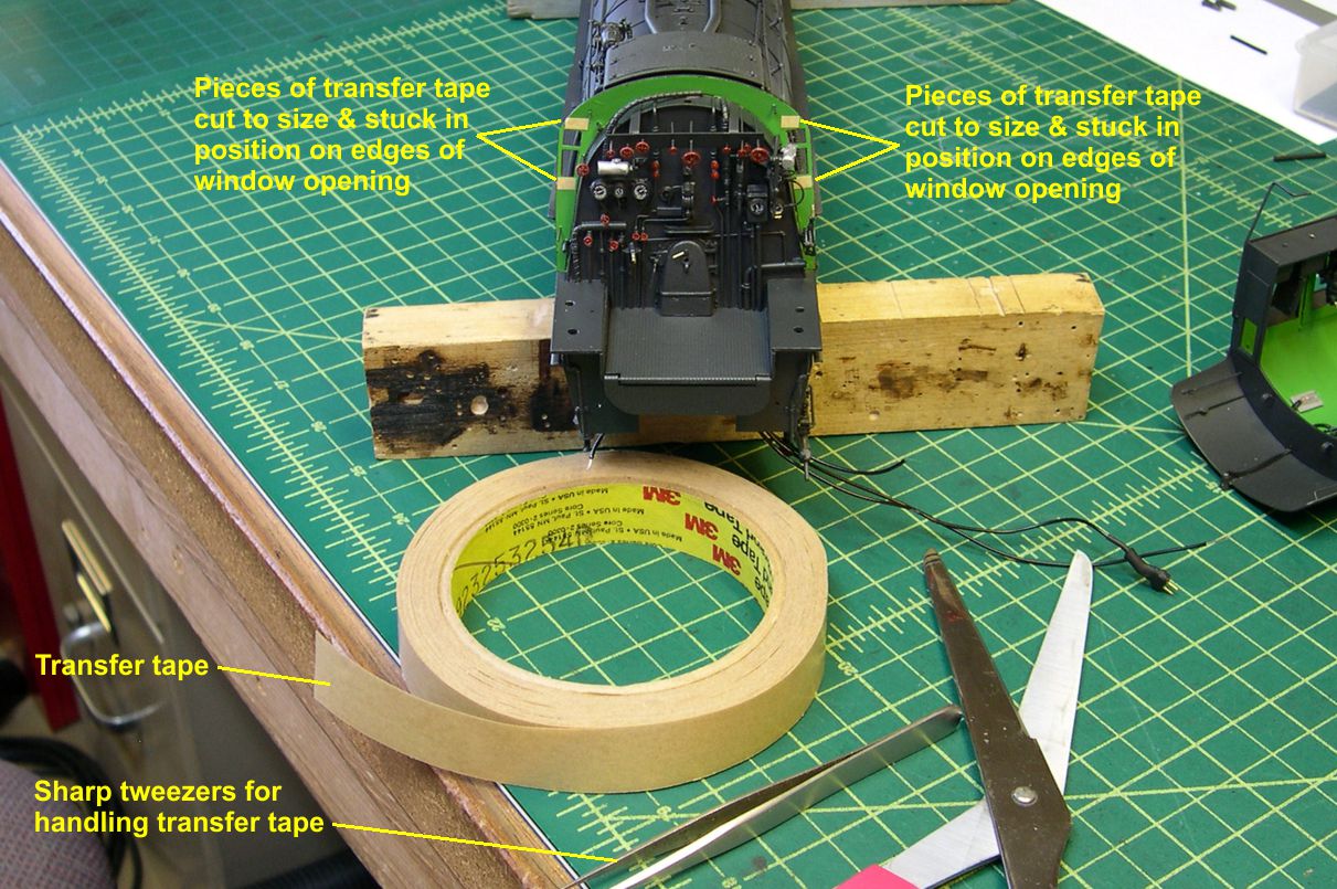
The paper backing is still on those pieces. You just pull off the paper backing and press the window glass into the adhesive. You can see how that looks in photo 4.
window glass 4 ⤵
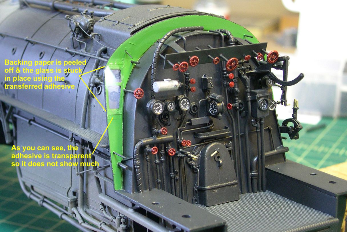
I should mention here that you use so little of the transfer adhesive that a single roll is a lifetime supply. I have been using the same roll for several decades, and it never seems to deteriorate. Cost per model is negligible. You can, of course, use this same transfer adhesive for many other materials as well.
Finally, I am going to discuss how I get reasonably uniform lighting in my number boards. See photos “No Brds-16 thru 22”. For years, I struggled with too many wires inside the number boards that shadowed the light or interfered with the proper placement of the bulbs. I finally found a nice solution. In photo 16, you can see how I cut off the long leads on the bulbs and stripped the insulation off the remaining wire on the bulbs.
number boards 16 ⤵
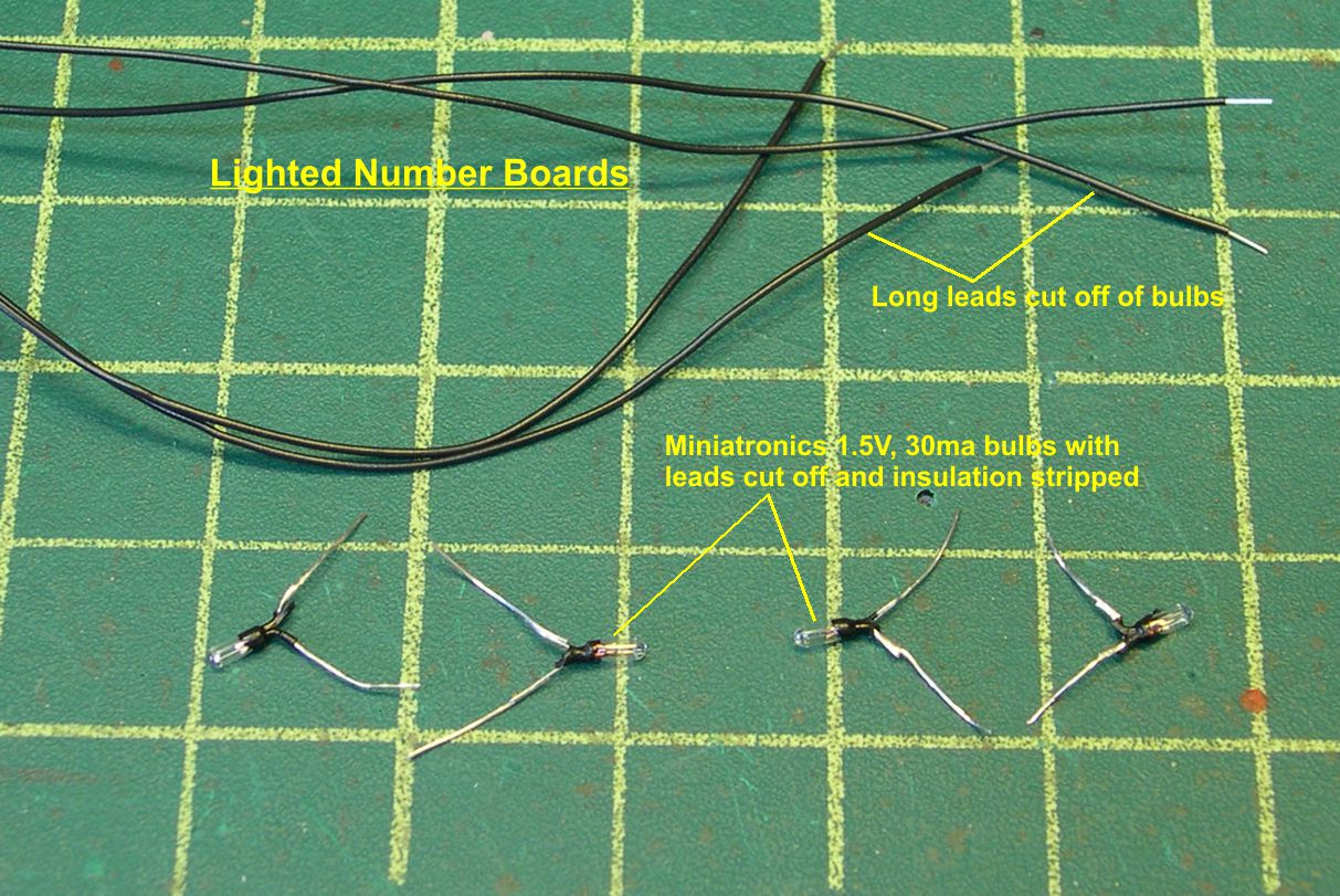
Then I twist the short leads together so the bulbs are in parallel, then twist one of the long leads onto each short one from behind. After soldering, I cut off nearly all the leads leaving short stubs as shown in photos 17 and 18.
number boards 17 ⤵

number boards 18 ⤵

Then I coat the stubs and bases of the bulbs with a thin layer of gap filling Zap ACC. This forms an insulation so I don’t get any shorts from the stubs contacting the inside of the number boards. When I insert the wires into the hole in the back of the number board, there is hardly anything inside the number board except the two bulbs. That makes positioning of the bulbs a piece of cake.
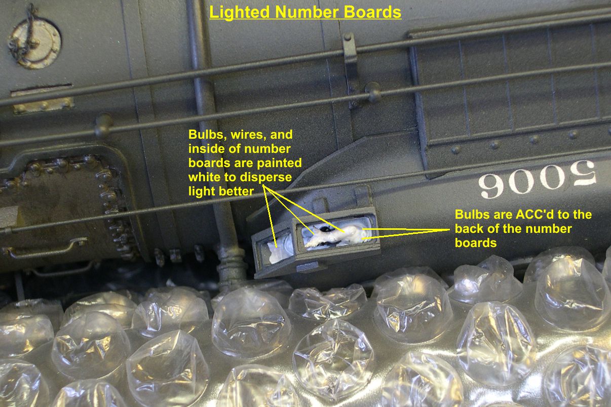
Once the bulbs are in position, I glue them in place with the gap filling ACC and paint the bulbs and inside of the number boards white. The white paint diffuses the light and makes the final effect much more uniform. This step is illustrated in photo 19.
number boards 19 ⤵
In photo 20, I have illuminated the bulbs to show how diffused the light is.
number boards 20 ⤵
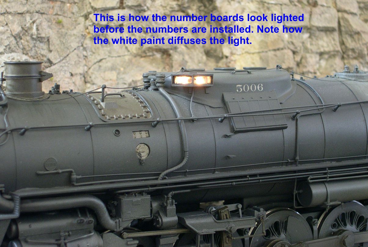
Photo 21 shows the final result with the numbers installed in the number boards.
number boards 21 ⤵
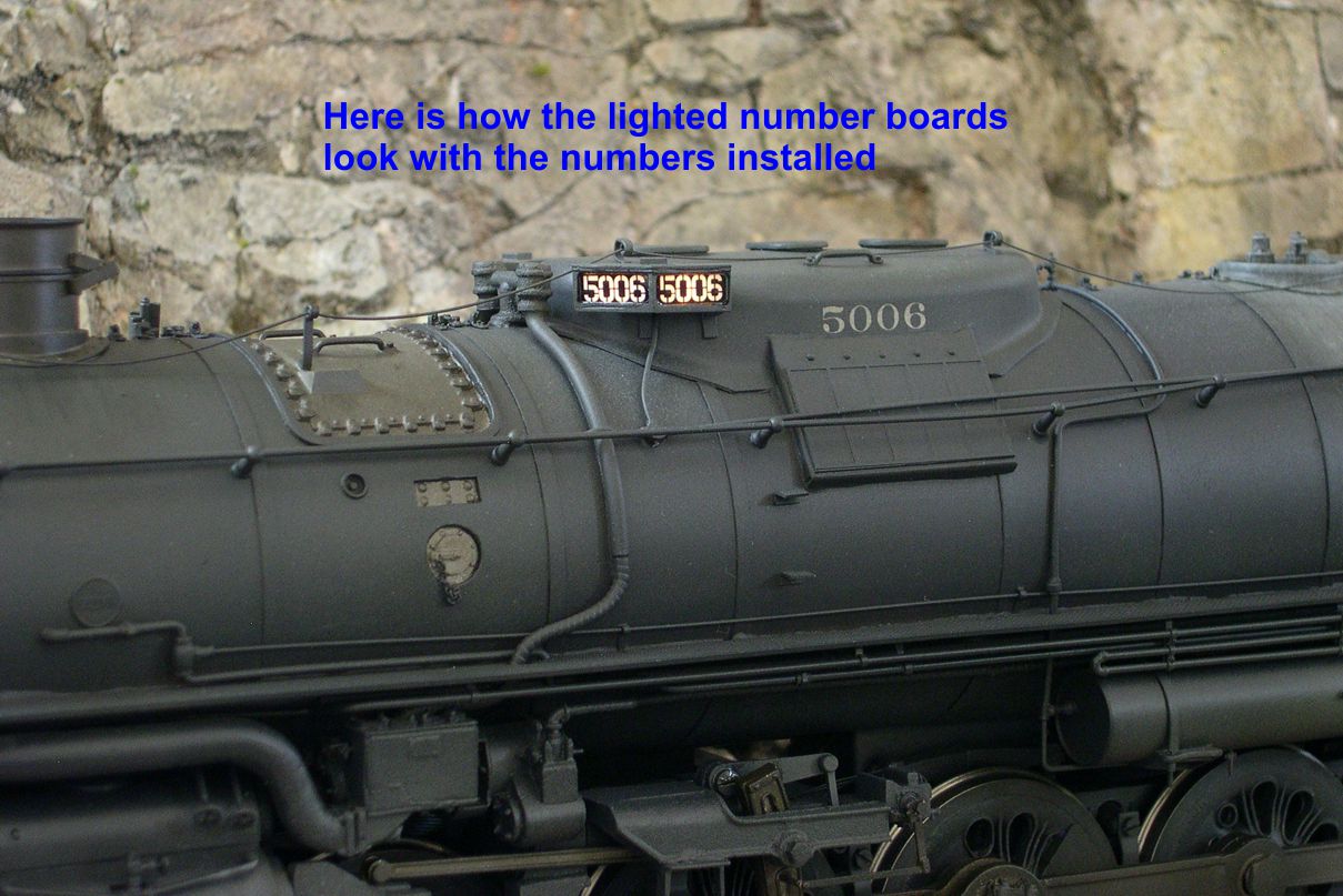
You don’t have that single hot spot of light so obvious in many model number boards.
Photo 22 shows how I make my numbers that go into the number boards.
number boards 22 ⤵
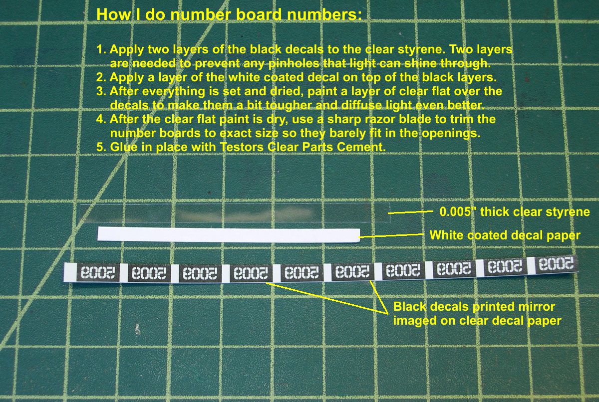
I make mirror imaged decals of the numbers so I can apply them to the backside of the clear styrene. I apply two layers of the black, line on line. One layer will leave some pinholes that light can shine through to ruin the illusion. The third decal layer is white coated decal film from Micro Mark. It makes the numbers look white when the lights are not on, just like the frosted glass on the prototype does. The white is quite translucent though, so the light shines through it when the lights are on. I add a coat of clear flat paint on top of the decal layers to protect them during the handling of installation. When you turn the number plates over, the numbers read correctly and appear to be behind glass as on the prototype. Carefully trim each number plate to fit exactly in the space on the number board and mount it with Testors Clear Parts Adhesive. You can see in photo 21 how effective these number plates are.