AT&SF Class 5001 Tank Brackets
There are 16 photos attached showing how I built the “faux” brackets for the air tanks on these two 5001 class 2-10-4’s. I call them “faux” brackets, because they are actually built up on the tanks rather than being used to mount and support the tanks originally. In reality, now that they are finished, the bracket facades provide a lot of strength, probably as much as the original hidden brackets do. What I have tried to do is duplicate the appearance of the cast brackets the ATSF used. This whole air tank thing has become more complex and time consuming than many whole engine projects. These are not simple artifacts to attach to an engine.
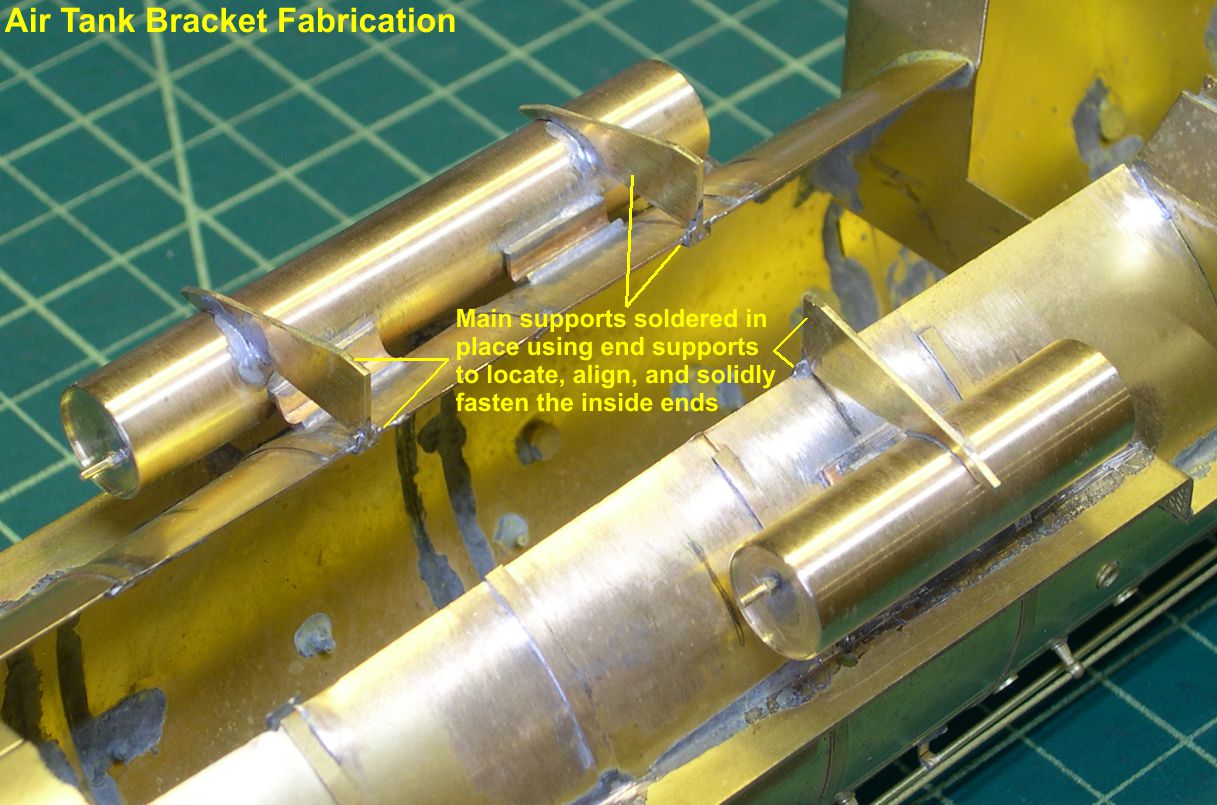
In photo 1 you can see the main support element for one engine’s worth of brackets.
photo 1 ⤵

They are cut from 0.032″ brass strip and filed to shape. I did not want to simply butt solder the large end to the edge of the boiler, as that would be a very weak joint, so I came up with a simple little end support that was easy to make, easy to solder in place, and served as a locator for soldering the main support while supplying a lot of extra surface and strength to the solder joint at the large end of the main support. The end supports were simply cut off pieces of brass angle from Special Shapes. I used my Dremel to cut a slot in one side of each one. That slot holds the end of the main support. Photo 2 shows the end supports soldered in place on the edge of the boiler, and photo 3 shows the main supports soldered to the tanks and the boiler.
photo 2 ⤵
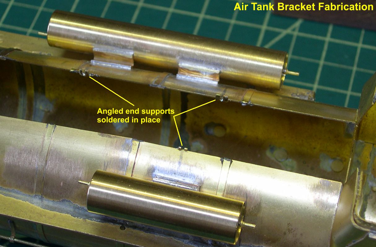
photo 3 ⤵
Soldering those main supports straight and vertical was MUCH easier using those end supports.
In photo 4, you can see the ends of the cast brackets after shaping.
photo 4 ⤵
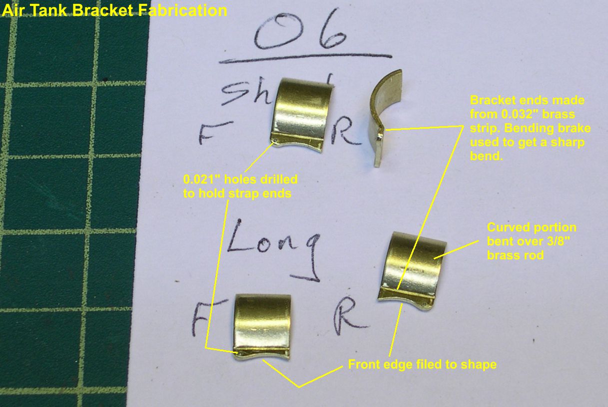
I used a bending brake (NWSL Bender) to put a sharp bend in 0.032″ brass strip. Then I clamped the short, bent end in a vise and bent the curved portion around a 3/8″ brass rod. Of course, when you bend something like this, it tends to spring back a little, which is why I used a 3/8″ (0.375″) rod to get approximately a 0.47″ diameter curve to fit the tanks. A little tweaking of each was necessary for a perfect fit onto the tanks. The sculpted front edge was done to match photos of the cast brackets. A 0.021″ diameter hole was drilled as shown in the photos for mounting the straps holding the tanks to the brackets. Again, what you see is the parts for one engine. Photos 5 and 6 show how the bracket ends look soldered to the main supports and the tanks.
photo 5 ⤵
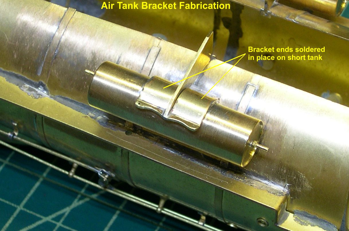
photo 6 ⤵
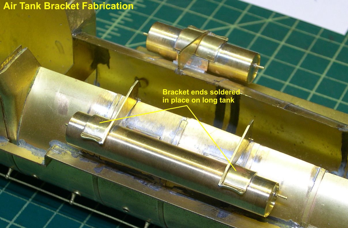
Now they are starting to look like cast brackets.
To complete the cast bracket appearance, I had to make a whole bunch of little tiny angled pieces from 0.016″ X 0.032″ brass strip as seen in photo 7.
photo 7 ⤵
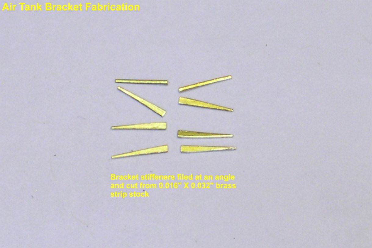
There are 8 parts per engine. Photos 8, 9, and 10 show these small stiffeners soldered in place completing the cast bracket illusion.
photo 8 ⤵
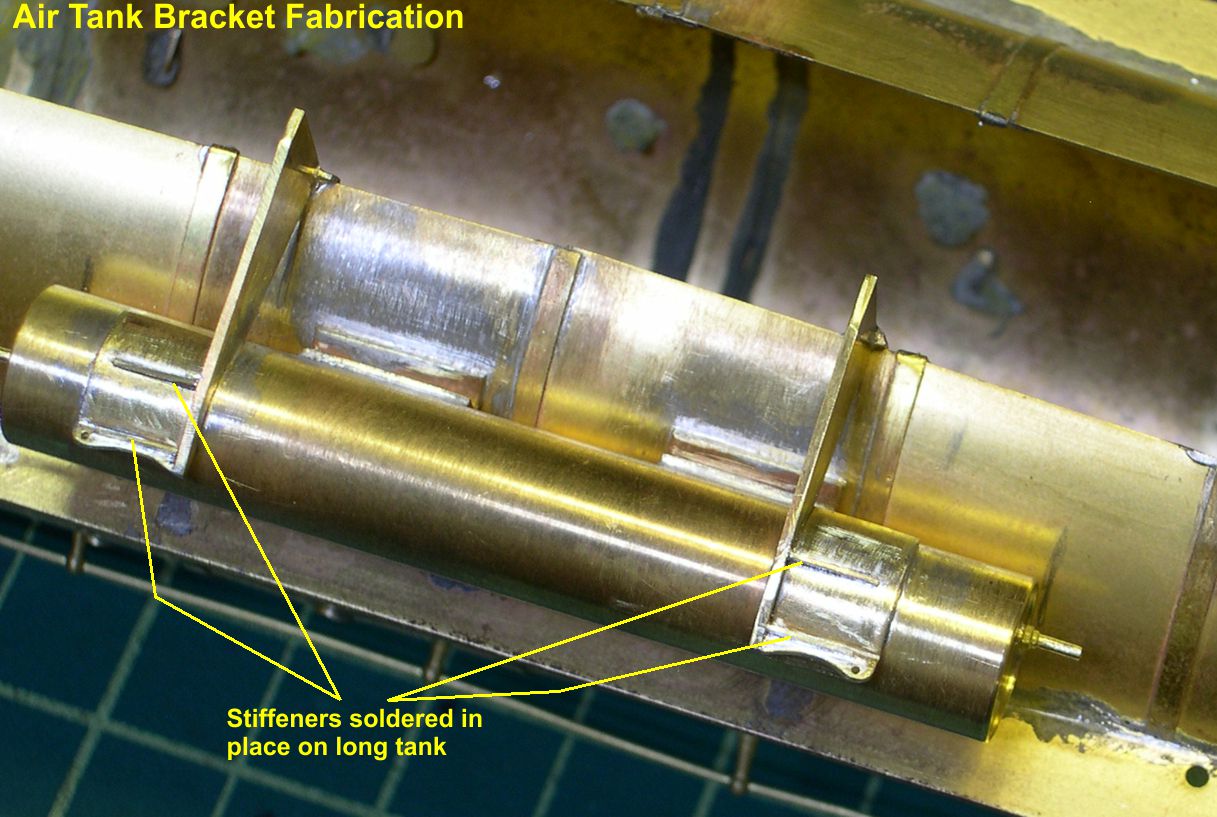
photo 9 ⤵
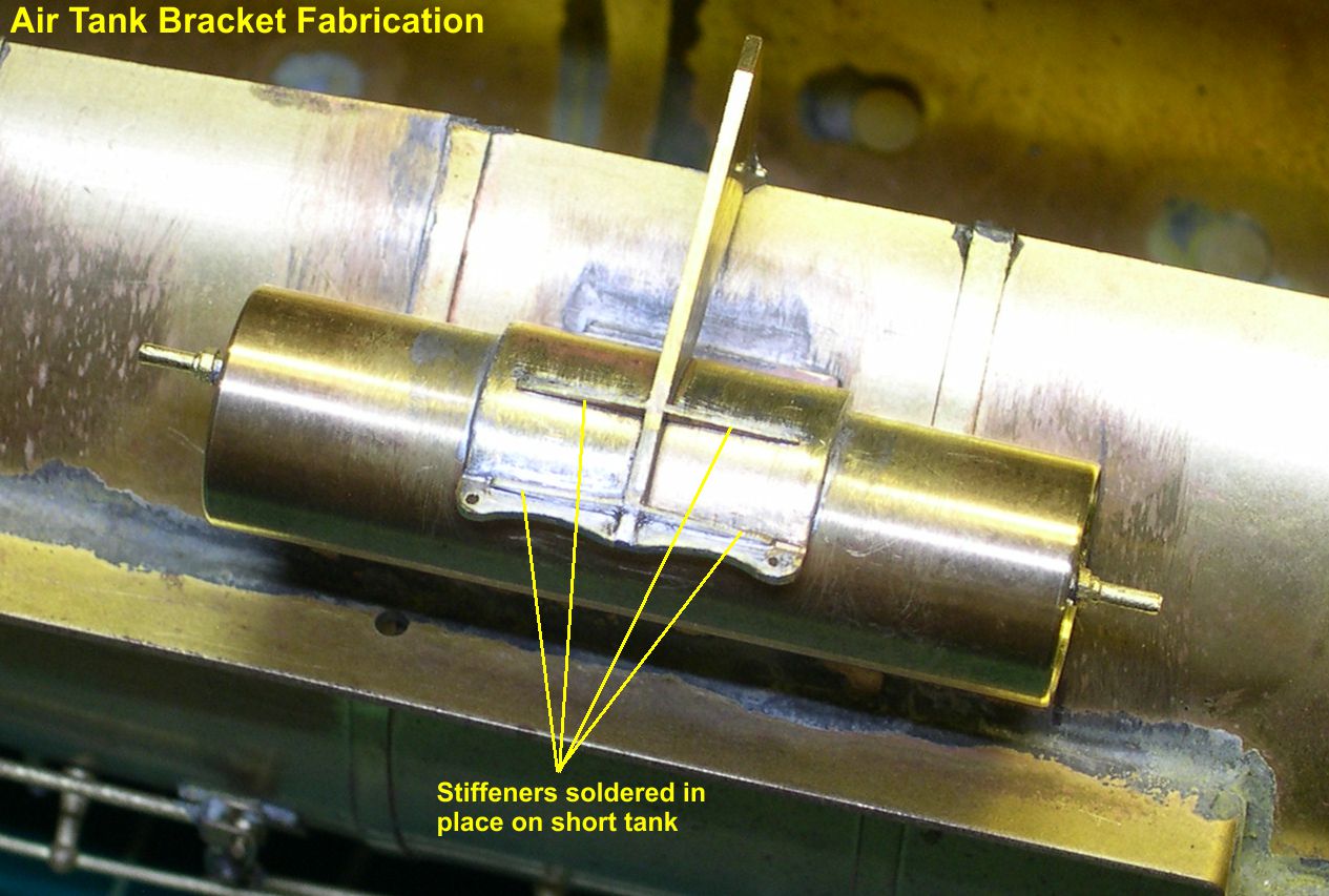
photo 10 ⤵
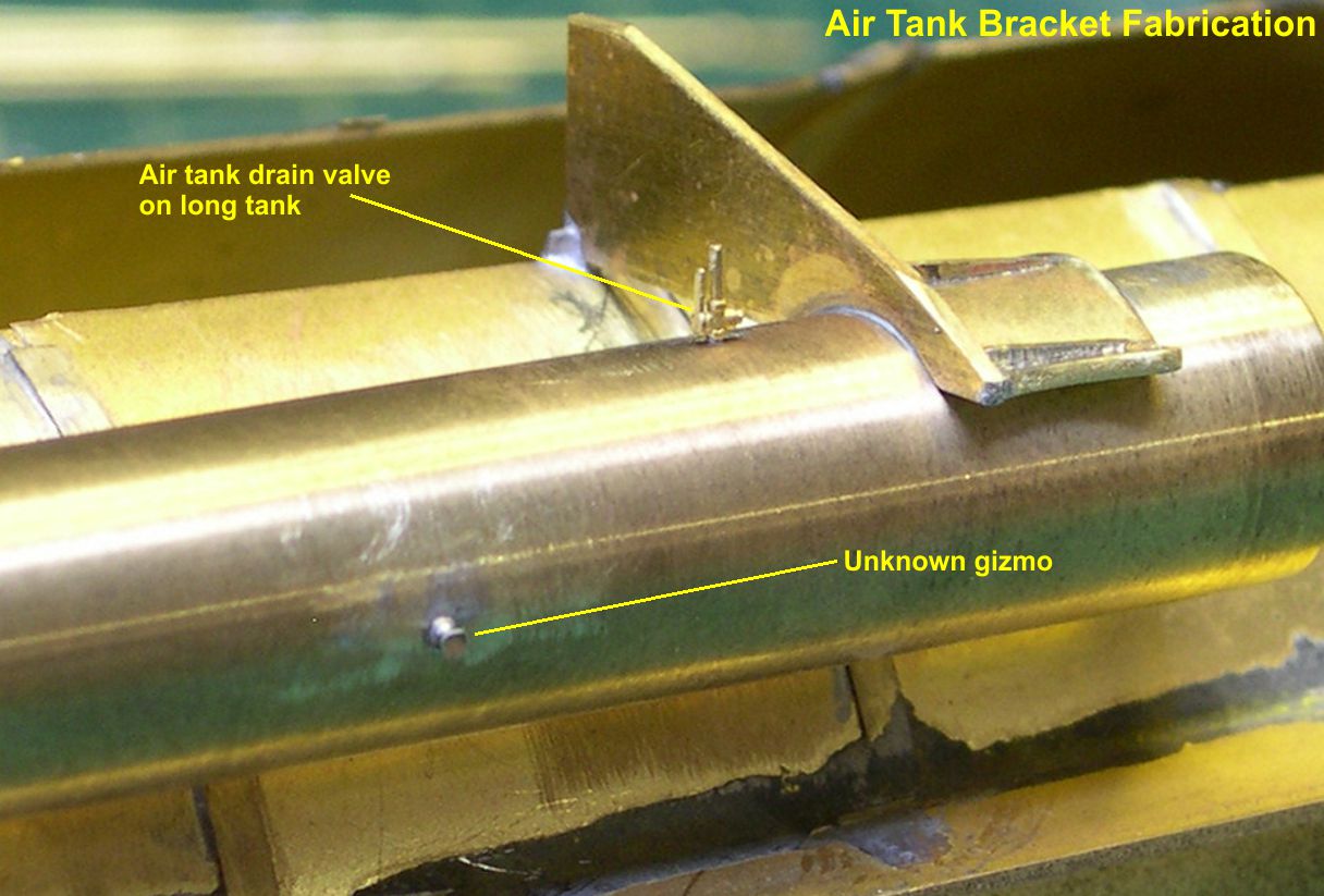
Before doing the straps that hold the tanks in place, I thought it would be good to add a couple of pieces of detail to the tanks themselves. Each tank has a drain valve (PSC casting) on the bottom and some weird gizmo on the side. I do not know what that gizmo is, but it is pretty simple. There is a flat fitting on the tank and a small shaft with a round, flat top. It almost looks like a pressure relief plunger, where you could press the rod in and evacuate the pressure in the tank. I don’t know why you would need such a thing given that you could just open the drain valve to do the same thing. Maybe it’s just a hook to hang your jacket on while you oil around or grease the rods. Anyway, I made a small turning for the rod and flat top and used a 0.5mm washer from Scale Hardware for the tank fitting. It looks exactly like the prototype, so whatever it was used for, my scale enginemen can get the same use out of it. Photos 11, 12, and 13 show these tank fittings.
photo 11 ⤵

photo 12 ⤵
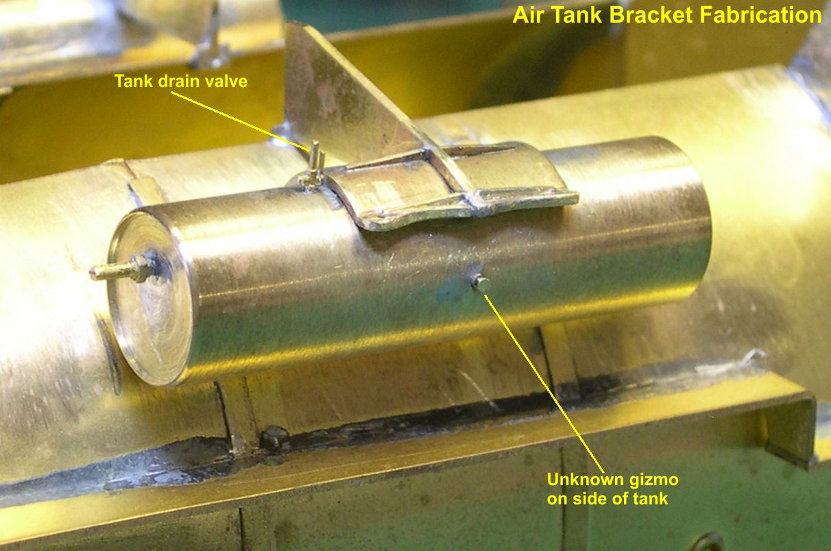
photo 13 ⤵
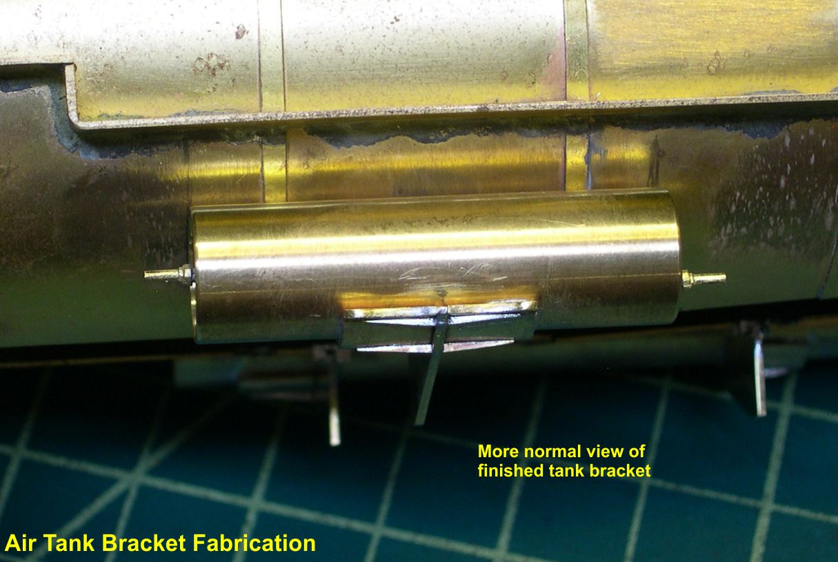
Finally, the straps for holding the tanks to the brackets were fitted and soldered in place. On the prototype, the ends of the straps were narrowed down and threaded. Then two nuts were used to lock the strap in place as seen in photos 14, 15, and 16.
photo 14 ⤵
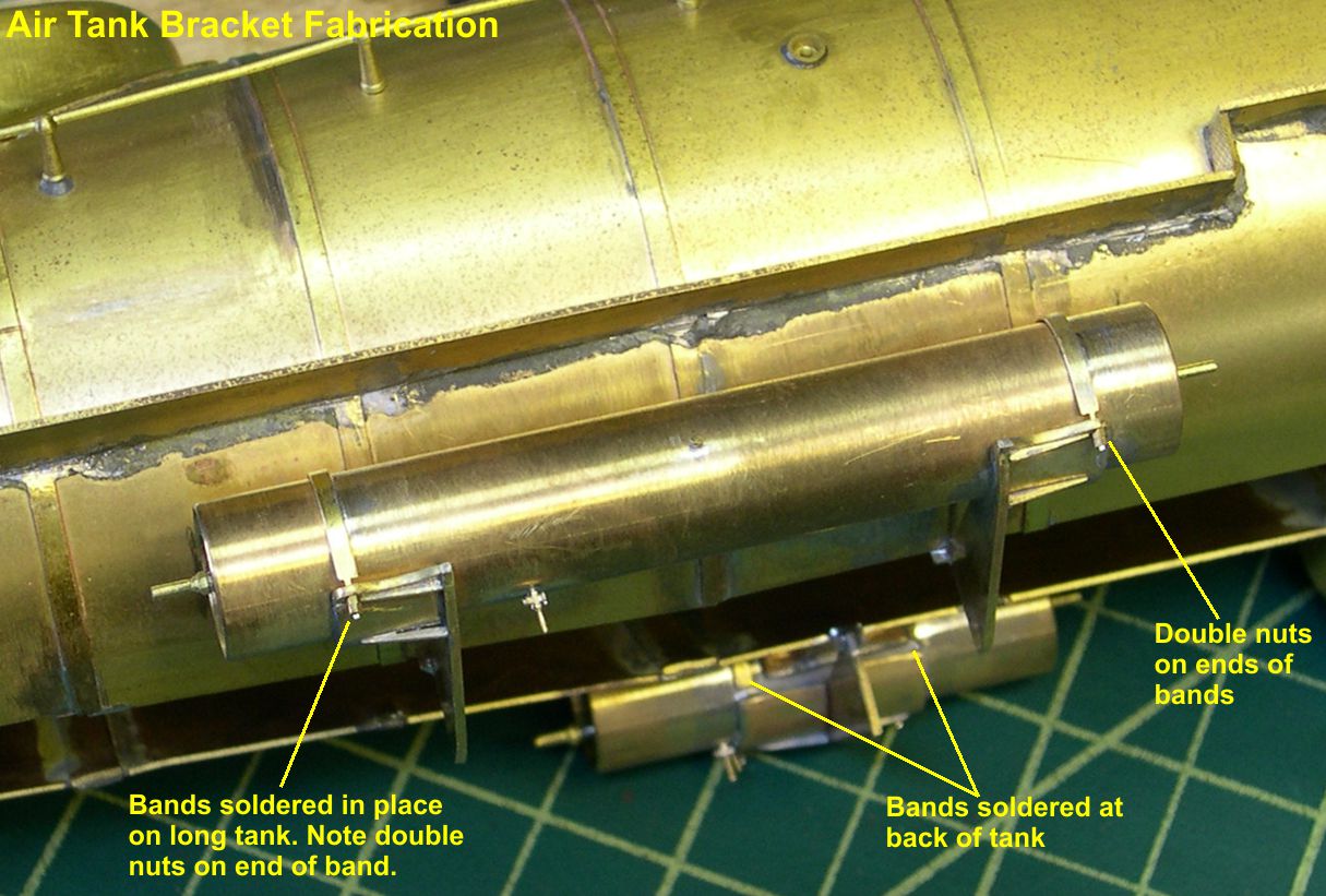
photo 15 ⤵
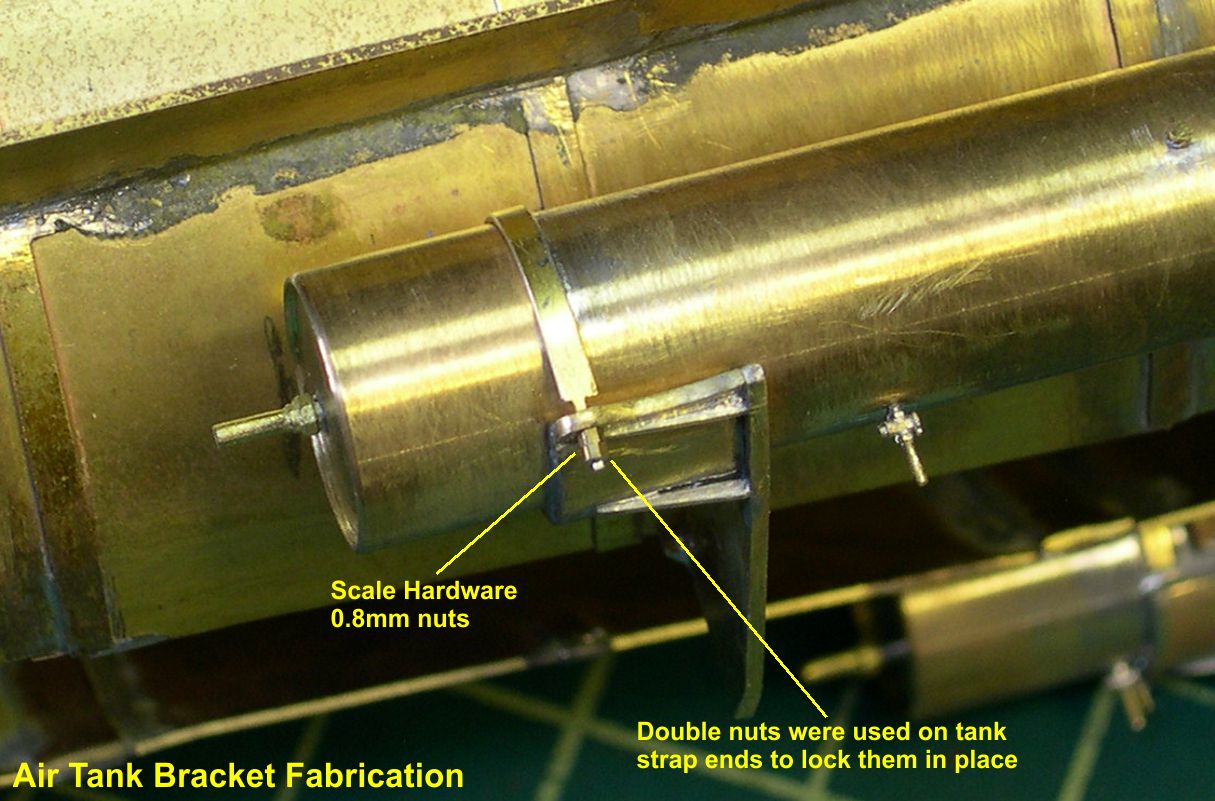
photo 16 ⤵

I used 0.8mm nuts from Scale Hardware for the nuts. That completes the tanks and their brackets. Now I have to plumb them.