AT&SF Class 5001 Frame Adjustments 1
I am going to go into a LOT of detail on this particular project, as it involves the use of numerous techniques and skills a lot of people would like to have. We will get right down into the weeds from time to time in an effort to explain exactly how certain things are done. This part of the project is a good example.
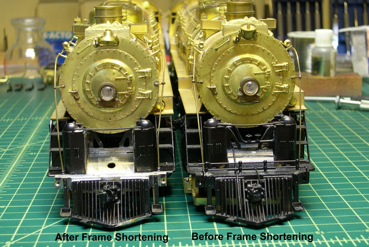
First of all, the 5001 class 2-10-4 had a significantly shorter pilot deck than the 5011 class. It also did not rise as high above the lead truck. This is all probably explained by the larger diameter lead truck on the 5011 class. In order to do a reasonably accurate model of the 5001 class, I needed to modify the front of the frame in order to incorporate the differences. I have included 2 photos (1 and 2) that are basically “before and after” photos with the unmodified USH 5011 sitting right next to my modified 5001 model. It is obvious how the pilot sticks out farther on the 5011 and the deck between the air pumps rises higher before descending to the pilot beam.
photo 1 ⤵
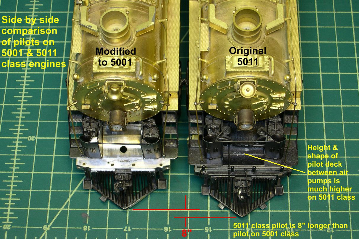
photo 2 ⤵
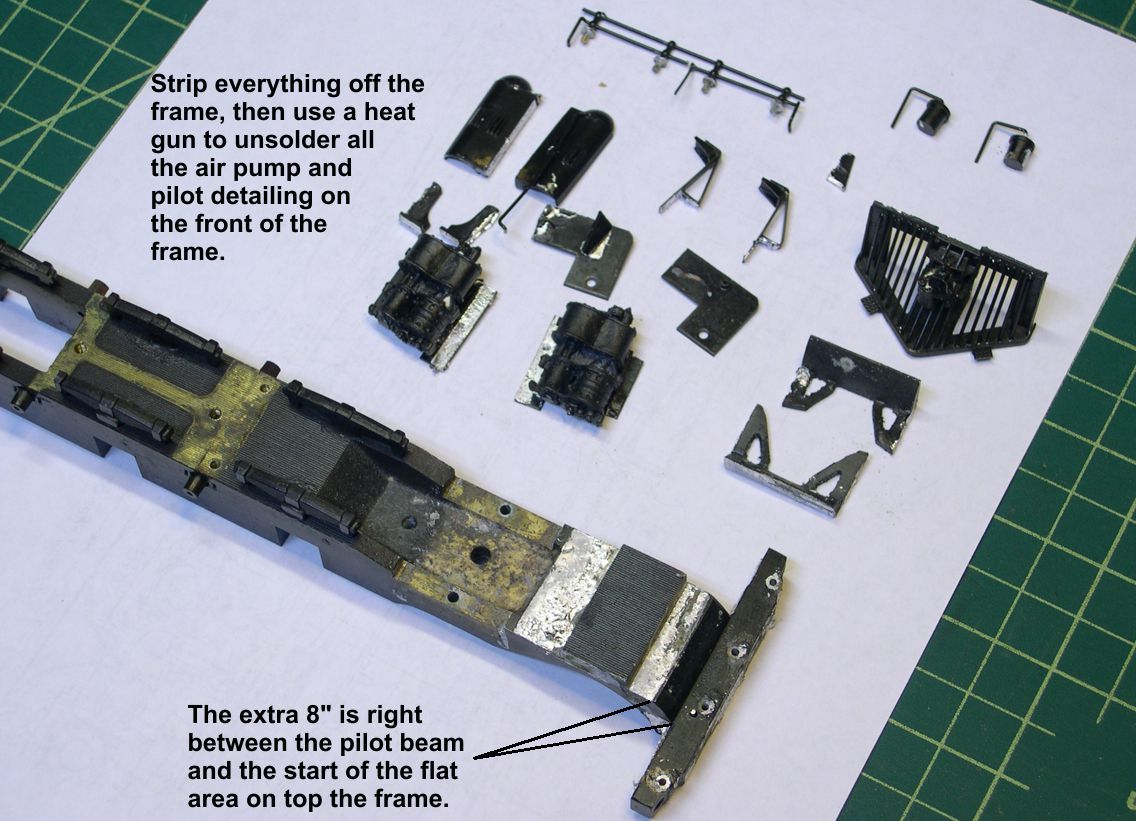
The first step is to completely strip everything off the frame – all the running gear, motor, etc. Then I used my heat gun, which can produce heat above the melting point of solder on its highest setting, to unsolder all the air pump and pilot detailing on the front of the frame. Photo 3 shows how the front of the frame looks after this unsoldering operation. The section of frame to be removed is noted at the bottom of the photo.
photo 3 ⤵
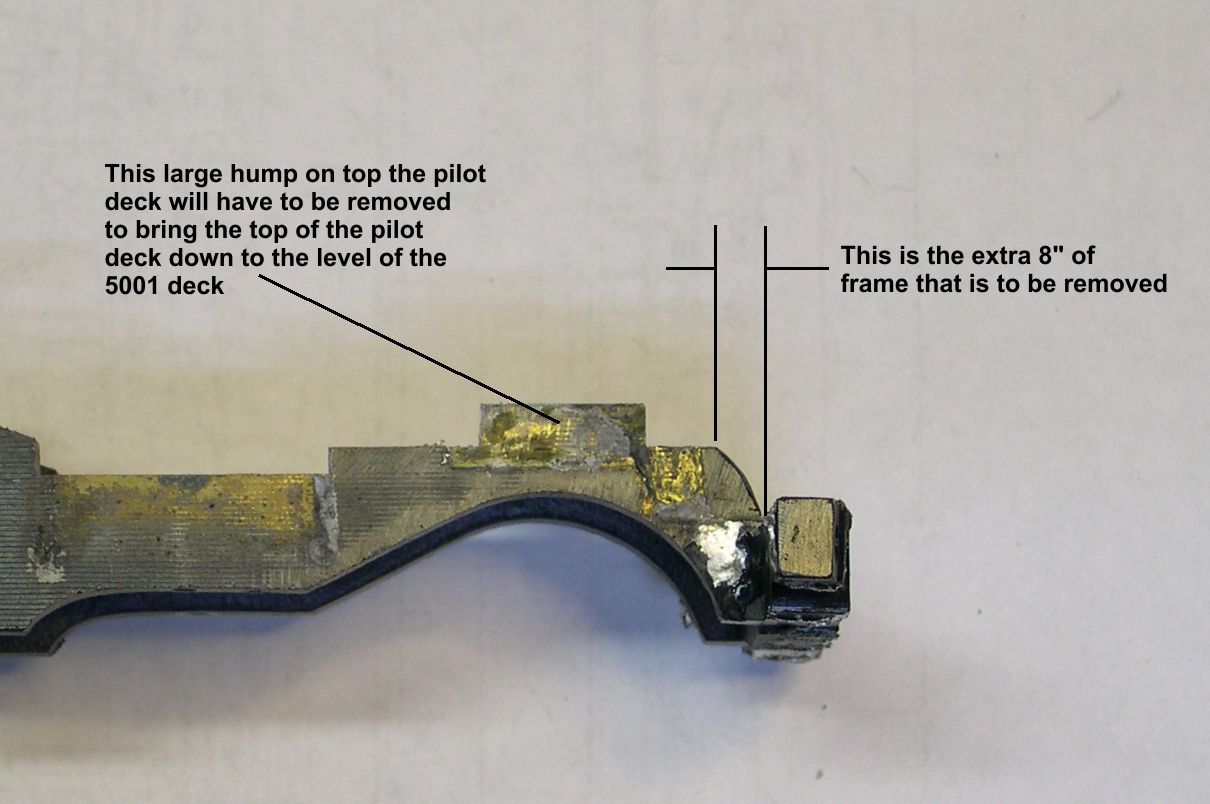
In photo 4, a side view, you can see the section to be removed and the large rectangular hump on top the frame that will also be removed.
photo 4 ⤵
The modification is started by clamping the frame in a large vise and using a standard hacksaw to separate the pilot beam from the rest of the frame casting as shown in photos 5 and 6.
photo 5 ⤵
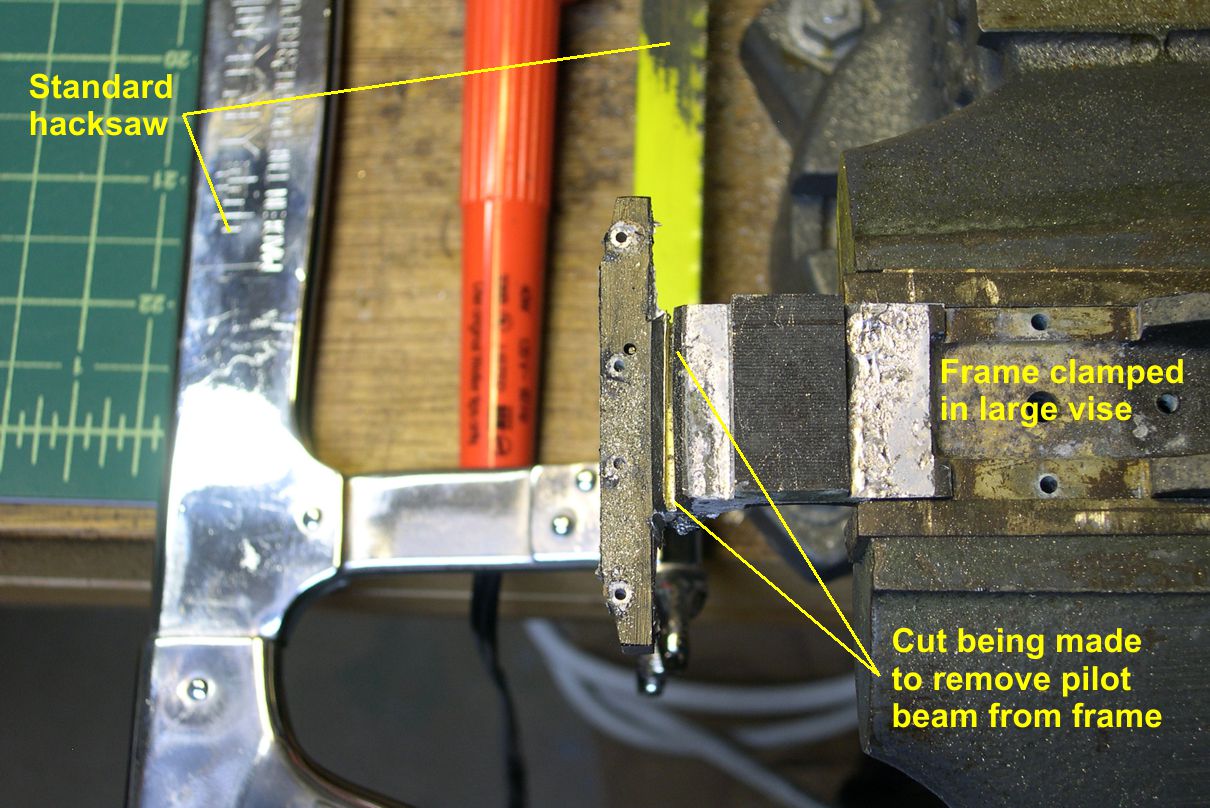
photo 6 ⤵
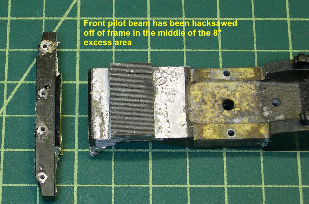
The cut is made down the center of the section to be removed so I can use precision machining to clean up and true both surfaces before soldering them together.
I used my Sherline mill to make all the precision machining modifications, and there are a series of photos showing how to clamp the frame to the bed of the mill, etc. While doing the machining for modifying the frame’s length, it is convenient to include a fix for the engine’s ability to go around curves. Anyone who has tried to get one of these USH 2-10-4’s to go around anything sharper than about a 90″ radius knows that they are very long and stiff. If you have one that will easily traverse a 72″ curve, I guarantee it has been modified. A stock one cannot do that.
The ATSF 5001 and 5011 class 2-10-4’s had the longest cast steel engine bed ever cast for a steam engine. With 74″ drivers, they had a very long rigid wheelbase. Note that they were about the same length as many large, modern articulated engines, and they did NOT bend in the middle as the articulateds did. Even with lateral motion devices on the front drivers, the Santa Fe never even considered using them on Cajon or Tehachapi. They simply could not make the tight curves there. Only one ever visited California. The 5006 was used in the opening ceremonies for Los Angeles Union Passenger Terminal. The model has the same issues. There is insufficient side play in the drivers to allow these models to go around what we consider reasonable curves. I have 72″ minimum radii on my layout, and these models simply jump the track and keep going straight when entering a curve.
There are two ways to fix the problem. Years ago, I did not have a nice mill, so I disassembled all the driver sets and filed down the outside of the bearing blocks about 0.020-0.025″ leaving only about 0.010-0.015″ thick “ears” on the outside of the bearing blocks to keep them from sliding on through the slots in the frame. Experimentation both then and now has shown that ALL the wheelsets have to be able to move more from side to side, not just the front and rear ones. Did I mention that these are huge, stiff engines? Modifying the bearing blocks worked just fine, and I have had a 5011 class engine running on my layout for years with this modification. However, the bearing block mods are very time consuming, and many people would hesitate to disassemble all the wheelsets, since the re-assembly is not trivial. The alternative is to mill down the area around the slots in the frame about 0.025″ so the bearing blocks can slide further in the slots. You cannot go more than about 0.025″ or the backs of the drivers will start to contact the frame resulting in shorting. For those without a mill, you COULD just file a slot across the frame at each bearing slot, making it about 0.025″ deep. Since it would be hidden behind the disc drivers for the most part, it would not be too unsightly. However, that would also be pretty time consuming. This 0.025″ extra movement on each side for each driver set is sufficient to get the engines around 72″ curves quite easily. I suspect it might be good for down to 66″ or even 60″, but you might start to get into problems with the siderods hitting the crossheads. It’s tricky to get all the clearances right even at 72″ radius. If you have tighter curves than that, I recommend you sell your USH model and look for a Sunset one. They were made for 3-rail curves, so they can take very sharp curves indeed. They may look silly doing so, but at least they can do it, and the Sunset model is a pretty good one, too.
Photo 7 shows the milling around the bearing slots in progress.
photo 7 ⤵

Note how the frame is securely clamped to the bed of the mill. It is raised up on a brass block to clear the little mounting pieces for the brake hangers. There is another clamp out of the picture to the right. Milling is a very rough process, which is why mills are built so much more robustly than lathes are. You have to be sure the work is really secured to the bed and can not loosen up or you will make a mess. Photos 8 and 9 show the finished recesses around each bearing slot.
photo 8 ⤵

photo 9 ⤵
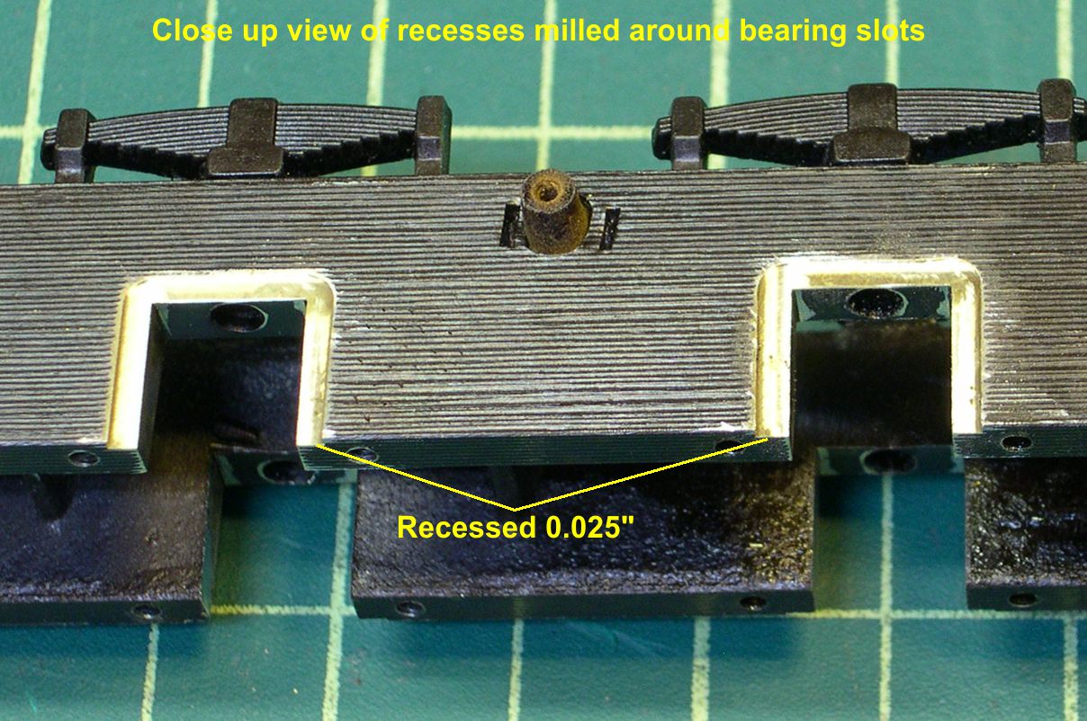
A little file clean up is necessary to remove any smeared brass around the edges. The driver sets, with their bearing blocks will fit right back into the frame as before, but they can now slide a lot further side to side.
Photo 10 shows the set up for finishing the front of the frame.
photo 10 ⤵
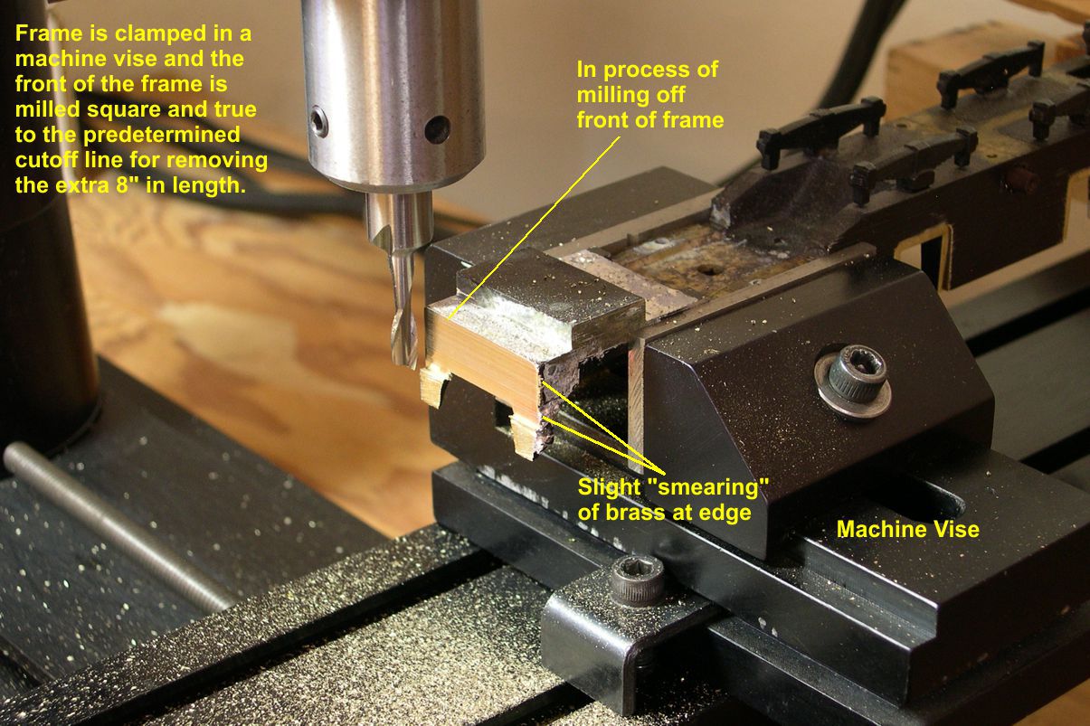
Recall that I sawed the frame apart leaving a little residue on both sides of the saw cut. This photo shows the residue being machined off square to the rest of the frame. The frame is tightly held in a machine vise. What you cannot see is that the rear of the frame is supported on some wood blocks, so the frame has no tendency to pivot down at the rear during machining. It is a heavy frame, and that would definitely be a risk without support at the rear. You mill repeatedly across the face going down about 0.030-0.050″ per pass. Don’t try to mill the whole thing on one pass. You could do so on a much larger mill, but the Sherline is a small mill for modeling purposes, not a big industrial grade machine. It is accurate to 0.0005″, but not if you try to take too big a bite. Brass is a pretty soft, maleable metal that tends to smear a little at the edges of a cut. I have pointed this out in photo 10. A little dressing of the edge with a file is required after finishing the work with the mill.
Photo 11 shows the set up for cutting off the big rectangular block on top the frame.
photo 11 ⤵
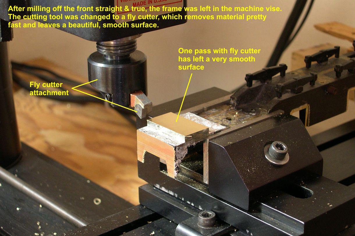
I have changed to a fly cutter for this operation, although the frame is still mounted the same way. For those not familiar with a fly cutter, it is a fixture that holds a normal lathe cutting tool at a slight angle as you can see in the photo. It will remove a lot of material in a big hurry and leave an extremely smooth surface behind, much smoother than a mill. The downside is that a fly cutter throws chips like crazy and they are HOT. You need a shield between you and the work to keep from being bombarded with uncomfortably hot chips, and the clean up is a bit worse, as the chips can travel a fair distance. I love using a fly cutter, as the surface is so good, but I treat the mill like is has a serious communicable disease when I have the fly cutter on it. It is a particularly dangerous tool due to its high speed and very efficient cutting capability. Just exercise due caution when using one. You can see the very nice surface it leaves on top the rectangular block, as I have made one pass already. You can also see the finished front of the frame after the milling on it was completed. In photo 12, the block has been completely removed. I went a few mils into the areas behind and ahead of the block to skin off the residual solder and leave a nice surface across the whole top of the frame.
photo 12 ⤵

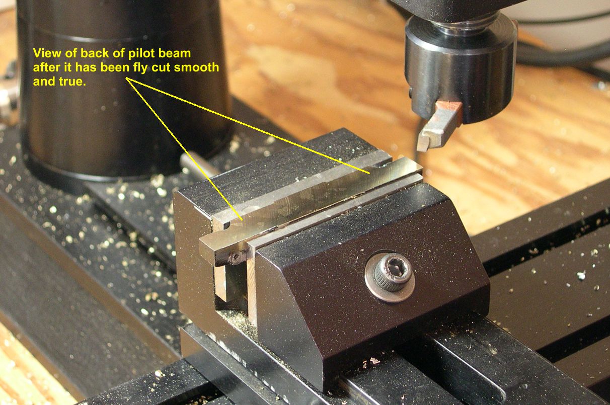
I used the fly cutter again to clean up the back of the pilot beam as seen in photos 13 and 14.
photo 13 ⤵
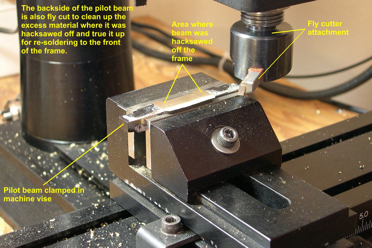
photo 14 ⤵
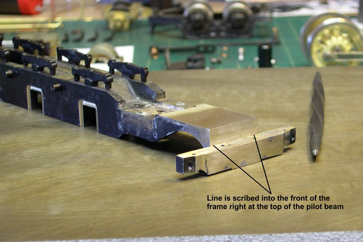
After a little cleanup of smeared edges with a file, I placed the frame and pilot beam on a flat steel plate as shown in photo 15.
photo 15 ⤵
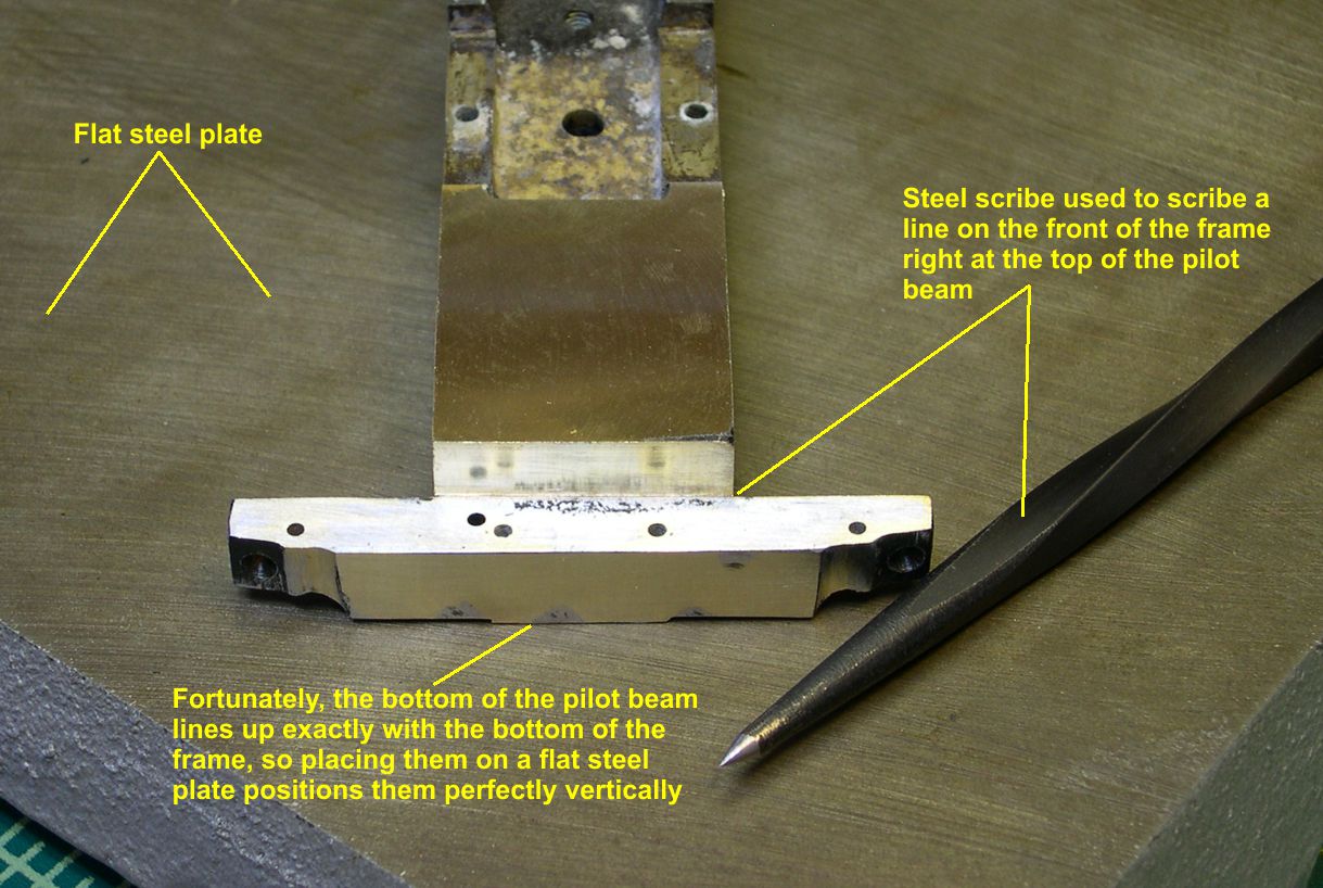
I was really lucky with this model as the bottom of the frame and the bottom of the pilot beam were exactly the same height above the rails. Hence, I did not have to do any shimming to get the pilot beam at the right height. All I had to do was place them both on the flat steel plate, and the vertical positioning was set. The frame has to be rounded on the front end to taper down from the basic frame height down to the pilot beam height. As noted in photos 15 and 16, I used a steel scribe to mark the front surface of the frame along the top edge of the pilot beam. The frame has to taper down to that line.
photo 16 ⤵
To facilitate measurements, I scanned an erecting drawing into my computer and sized it to be exactly O Scale. In photo 17, you can see the advantage to this.
photo 17 ⤵
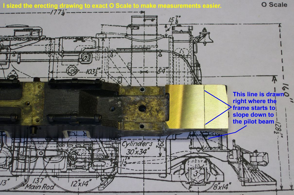
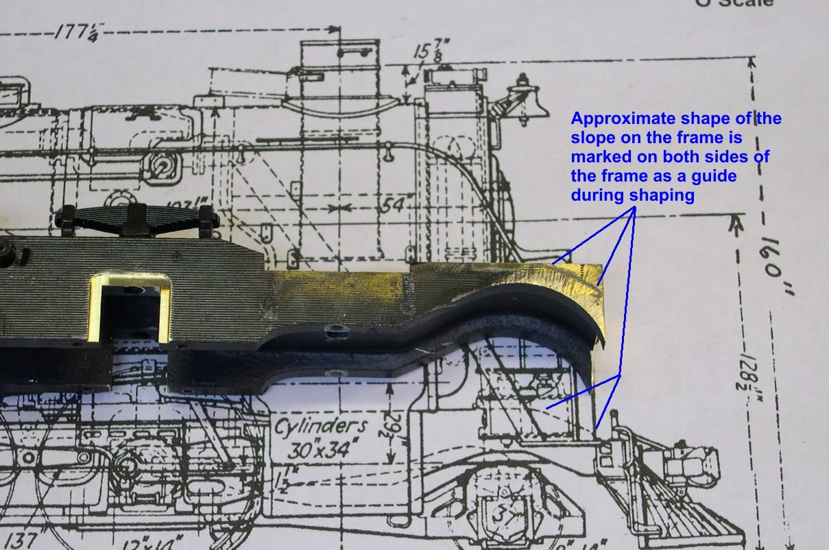
All I had to do was lay the frame on the drawing and draw a line where the frame starts to curve downward. I then sketched in the shape of the downward curve on both sides of the frame as shown in photo18.
photo 18 ⤵
Now we get to some real magic, which I have to credit to Mike Mangini. He told me about the success he has using a disc sander to quickly shape blocks of brass. He said the disc sander removed brass so fast I wouldn’t believe it. He was right!! Photo 19 shows the disc sander, which I have had for years and barely used at all. Turns out it will go through solid brass like a knife through butter. Better yet, it does not heat everything up like a grinding wheel does.
photo 19 ⤵
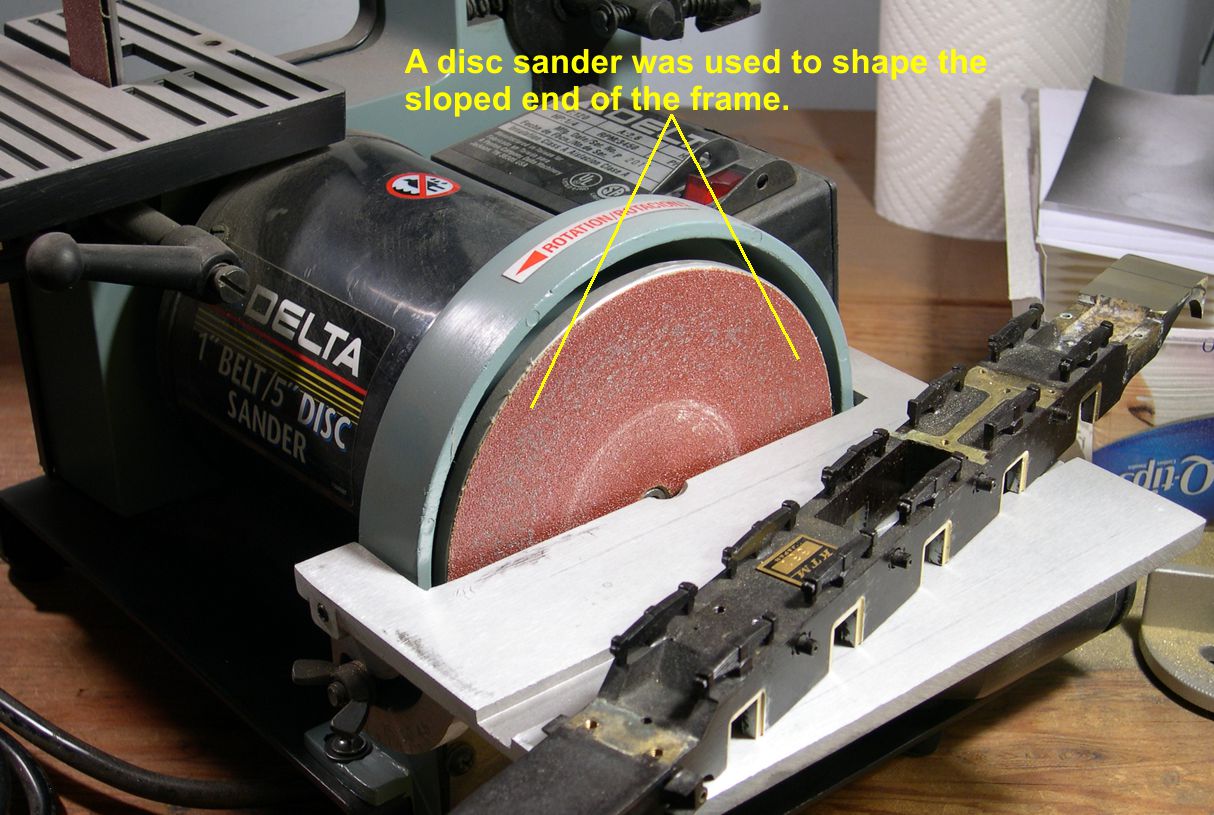
Somehow, it just converts the brass to dust with very little heating, muss, or fuss. What a great thing to know. Thanks, Mike. It only took me a couple of minutes to go from the square end on the frame to the shape shown in photo 20.
photo 20 ⤵
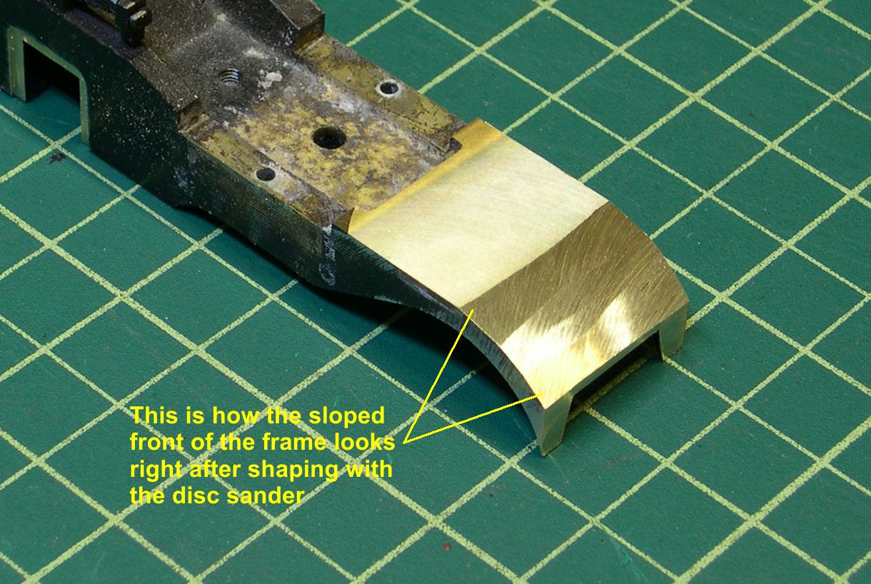
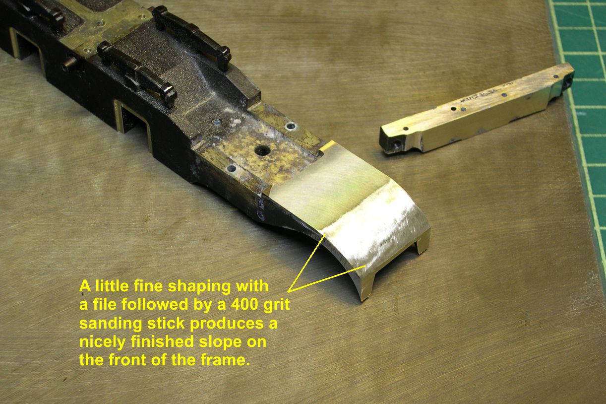
The main thing is to not go too fast and overrun your lines. You’ll never grind or mill such a shape anywhere near as fast. The disc sander just leaped way up my list of favorite tools. A few minutes with a fine file and 400 grit sanding stick produces the final result of the curved frame front shown in photo 21.
photo 21 ⤵
A lot of people have asked how to solder big, heavy pieces of brass together. Do I use a torch, or what? The answer is now revealed, see photo 22.
photo 22 ⤵
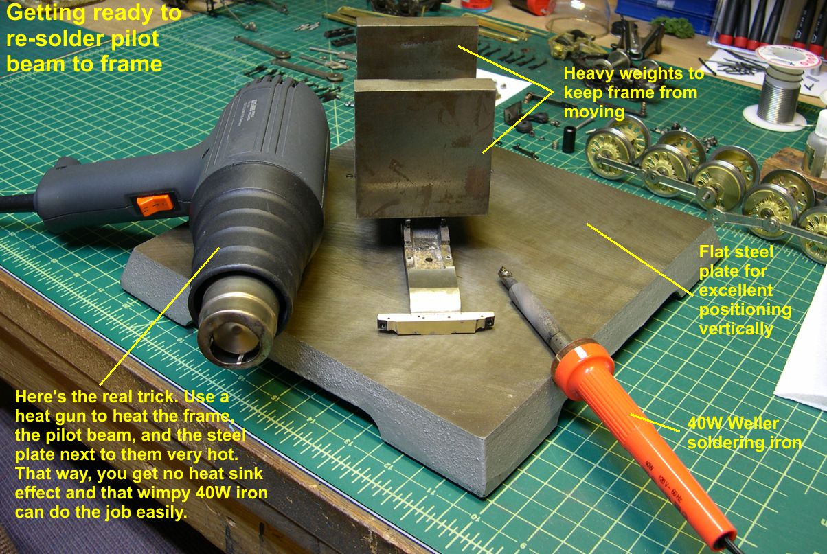
I use a medium sized 40W iron made by Weller (cheap and available in most hardware stores) coupled with a heat gun. The heat gun shown has two temperatures. One is hot, but well below the melting point of solder. This temperature is great for shrink tubing, which I use extensively. The second temperature is hotter than the melting point of solder, which is why I used it for disassembling the front end of the frame. It’s a lot safer than using a torch and does not warp thin brass so much due to its uniform heating. Ordinarily, I use the lower temperature, since I don’t want to disassemble anything, and heat up the pieces to be joined until they are too hot to touch. That ruins them as heat sinks, so a small iron can easily solder the big pieces of brass. (I fill up the heat sinks with heat, so they are no longer effective as heat sinks.) In this case, I can use the high heat to speed things up, since I have nothing to disassemble anyway. Also, with the pieces sitting on a heavy steel plate for accurate vertical positioning, the heat sink problem is much worse. Never fear, the heat gun can heat not only the pieces to be soldered but also the steel plate around the area to be soldered, so it is no longer a heat sink either. Just don’t rest your hand on the steel plate during the soldering . . . Notice also, that I have some heavy weights on the frame to keep it from moving during the soldering process. That way, I can use a long screwdriver to press the pilot beam up against the front of the frame without the frame skittering away and messing up my soldering job.
Before actually doing the soldering, let’s discuss the soldering technique itself. If you ever had a soldering course for electronics or wiring, you know to secure the PC Board or wires, then apply the resin core solder to the joint along with the iron. The solder will melt and run into the joint giving you a nice smooth solder joint. That is exactly right for electronics and wiring, but exactly wrong for soldering detail parts or even large parts to a model. For model work, you want to limit the amount of solder outside the joint to limit cleanup. Here’s how to do it. Clean the tip of your iron on a wet sponge so there is only a thin shiny film of solder on it. Touch the resin core solder wire to the iron to melt just a little solder onto the tip (only experience can tell you just how much is enough). The resin flux in the resin core solder immediately burns away leaving only solder on the tip. You then touch a brush with TIX Flux to the joint and let it flow into the joint. Then touch the tip of the iron to the joint and the solder will flow off the tip of the iron and into the joint. It is almost as it the TIX Flux literally sucks the solder into the joint. That is capillary action due to the TIX Flux nearly eliminating surface tension for the solder. Of course, the TIX Flux is also removing metal oxides allowing the solder and metal to bond. With experience, you can judge very closely how much solder to put on the tip of the iron to get a nice filled joint without a lot of excess to clean up. If you undershoot, just add more flux and more solder to the tip and re-apply to the joint until you get a nice strong joint. When using the heat gun technique, you may need to apply more heat before re-soldering.
To solder the pilot beam to the frame, I marked the pilot beam with a couple of small pencil marks to show where the sides of the frame should line up. Don’t try to do this by sight. Use a precision scale to measure and place the marks. Then the pilot beam is positioned up against the front of the frame as shown in the photos. Using the high setting on the heat gun, I got the two pieces to be soldered and the steel plate immediately around them very hot. Then I soldered the joint with the 40W iron using the technique described above and holding the pilot beam in place with a long screwdriver. You can see the result immediately after soldering in photo 23.
photo 23 ⤵
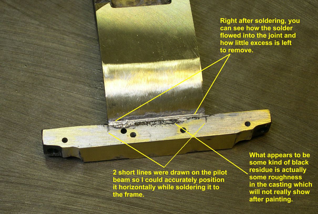
Note how little solder there is outside the joint, even on such a large joint in heavy brass pieces. Photo 24 shows what a bottle of TIX Flux looks like.
photo 24 ⤵
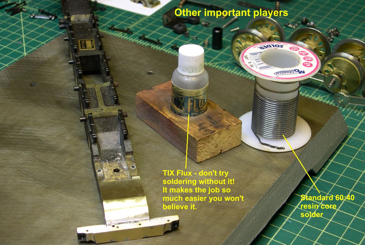
It will tip over very easily, so putting it in a block of wood as shown saves a lot of mess and replacement of flux. The solder shown is standard 60:40 electronic type resin core solder about 0.062″ diameter wire. I use the heavier wire for heavy jobs like this one. Most of the time, I use 0.020-0.032″ diameter wire. It is a lot easier to control how much solder you put on the tip with the smaller wire. In photo 25, I have turned the frame over to show you how the solder flowed throughout the joint and clear down to the bottom.
photo 25 ⤵

This is a very strong joint. After the frame cooled, I used a dull but smooth Xacto knife to cut and scrape away most of the excess solder. Then I finished up with a 400 grit sanding stick. You can see the finished joint in photo 26.
photo 26 ⤵
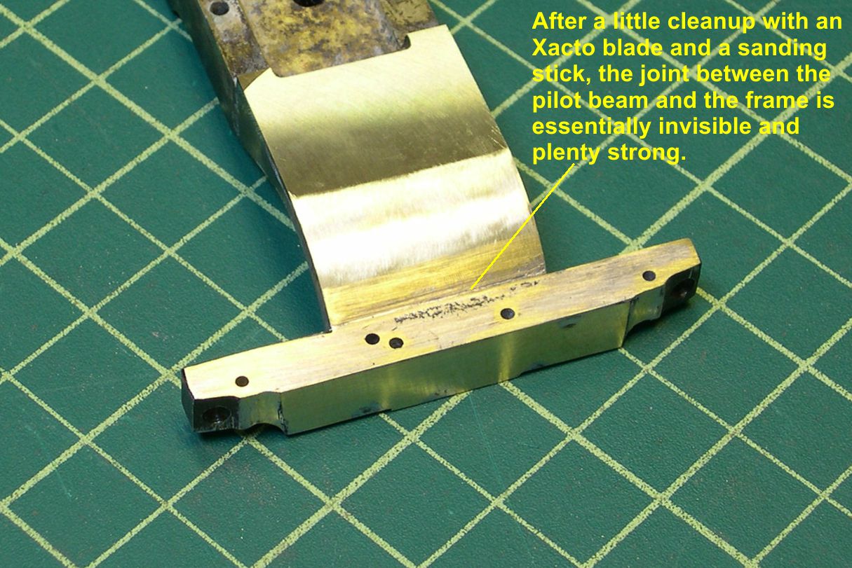
Due to the smooth surfaces and good soldering technique, it is hard to tell that there is even a joint there.
In the next part of this essay, I will be showing how to clean up and reassemble all those parts I removed from the front end.