AT&SF Class 5001 Stack – Feed Water Heater
Wow! Up to part 7 already and have hardly scratched the surface. Looks like I’ll set a new record for installments on this one. Well, onward and upward – namely up to the top of the smokebox now. The attached 16 photos show work on the stack and feedwater heater. The feedwater heater casting is really crude, so it has to go. The stack is held in place with a screw in the bottom of the stack. Sometimes, this is not too much of a problem with a narrow stack. You just paint the inside black and it’s hard to tell the stack doesn’t go on down into the smokebox. However, the huge stacks on these monster engines are the size of a grain silo, so you can’t hide the bottom of the stack. It has to go.
The first photo shows the top of the smokebox after stripping off the stack, number boards, feedwater heater, class lights, and whistle.
photo 1 ⤵
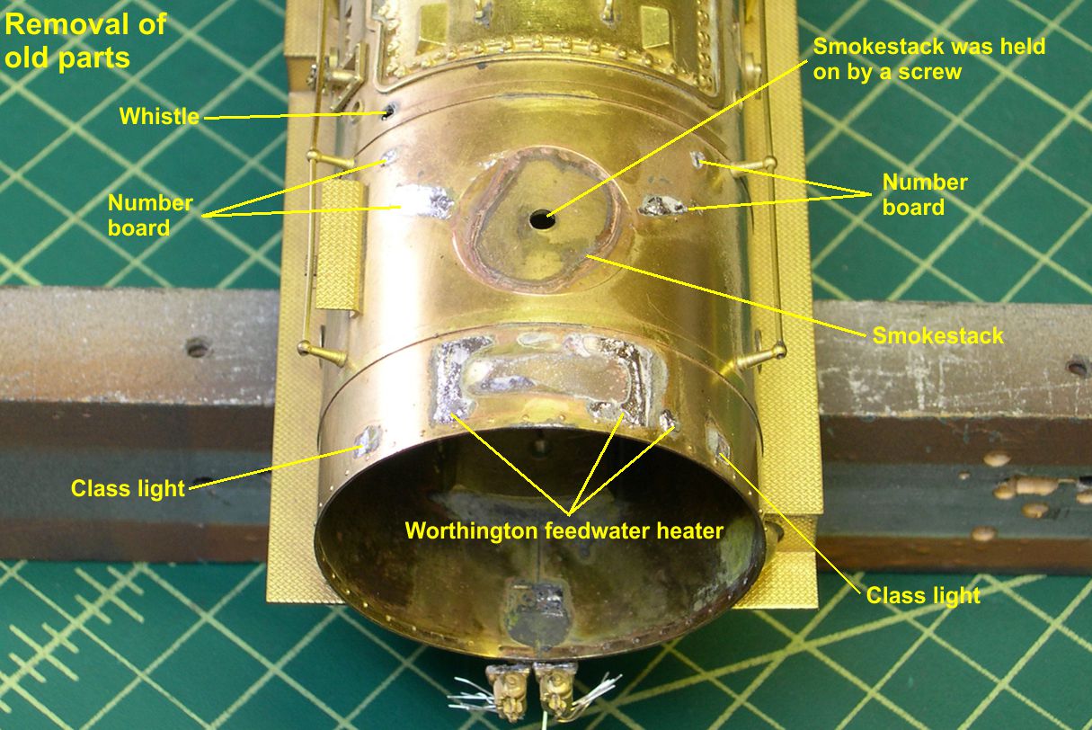
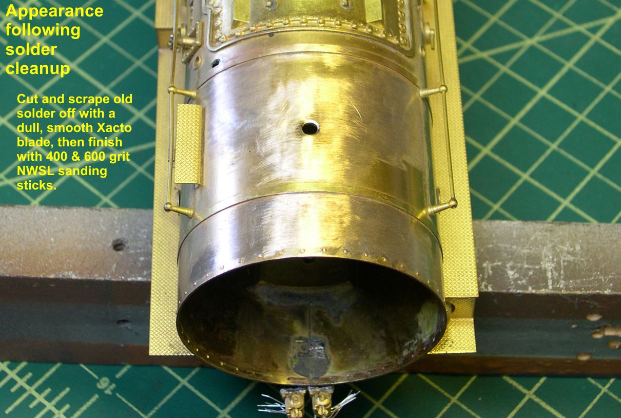
You can see how the stack was held on by a screw. Photo 2 shows how the same area looks after removal of the excess solder and smoothing of the surfaces preparatory to installing new parts.
photo 2 ⤵
The first item I tackled was the stack. It involves some rough work with the Dremel, so I wanted to get it out of the way before installing anything else. To remove the bottom of the stack, I had to disassemble the stack parts. The base of the stack is actually a machined casting, so it can be re-machined to remove the bottom. Photo 3 shows how to mount the base in the lathe chuck.
photo 3 ⤵

There is not much “meat” for the chuck to grab onto, so you have to use a machinists square to get the part concentric with the axis of the chuck. Place the square on the bed of the lathe as shown and make the top and bottom of the base touch the square. Then turn the chuck 90 degrees and repeat. Keep doing this until the base is touching the square top and bottom in any position, then tighten the chuck and re-check to be sure the base did not move. Now the base is held concentric with the axis of the chuck and the hole in the stack can be accurately machined with no wobble.
Do not even consider trying to drill out this nearly 1/2″ hole in one pass. There will be too much force exerted on the base and it could easily be ripped right out of the chuck and badly damaged. You really don’t want to have to make a new base, do you? The safe and accurate way to do this job is to start with small drill bits and work your way up in several steps to 1/4″. That is the size needed for a boring tool to work. The boring tool can enlarge the hole from there with very little effort or risk to the part. Photos 4-6 show this process.
photo 4 ⤵
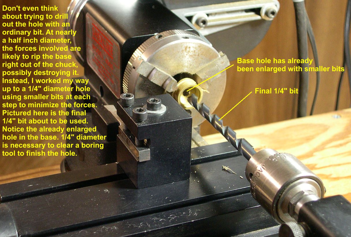
photo 5 ⤵

photo 6 ⤵
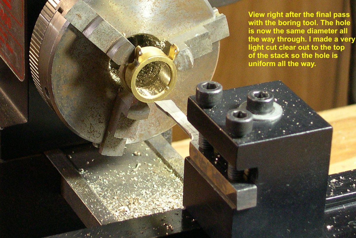
As the hole reaches the inside diameter of the stack base, make a light cut along the entire depth of the stack to give a nice smooth interior with no ridges, etc.
In photo 7, I show how the original flip over stacks were constructed.
photo 7 ⤵
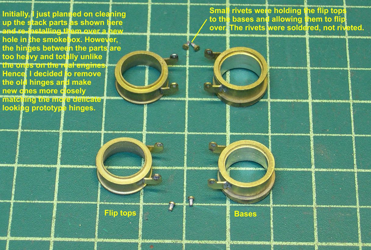
As noted in that photo, I really intended to just reassemble them as they existed. However, I noticed in photos that the actual prototype hinges were a lot more delicate looking and were connected side to side with a rod or axle for better alignment and strength. Consequently, I stripped off the original hinges and built up some that more closely resemble the real thing. The ATSF used some fancy castings for these hinges that would take forever to duplicate, so I decided to compromise with something close. After painting, it will not be very obvious.
Before cutting a large hole in the top of the smokebox to match the newly opened up stack, I used the small screw hole and screw to position the rivet ring that goes around the base of the stack. I then soldered it in place. Then I used my Dremel to open up the small screw hole until it was slightly larger than the inside diameter of the stack. That way, it would not be visible once the stack was soldered in place making extreme accuracy unnecessary. You can see this hole in photo 8.
photo 8 ⤵
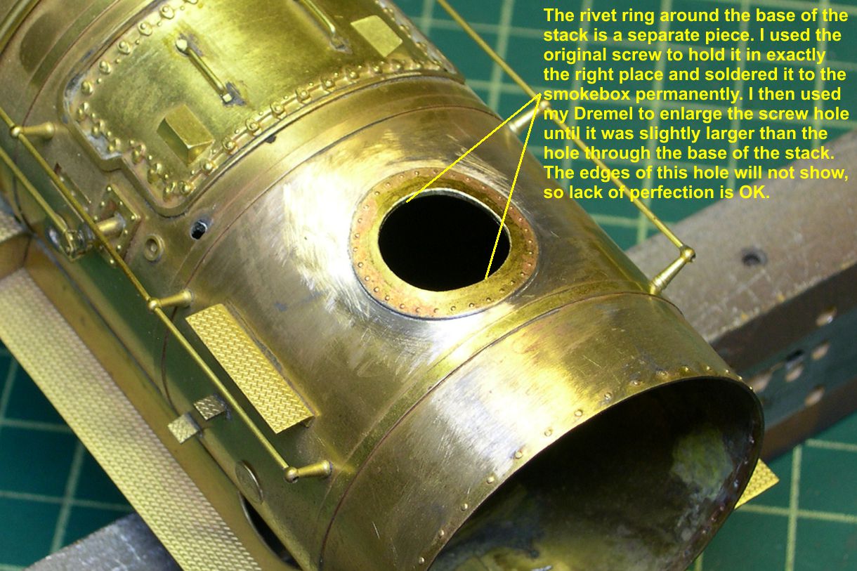
Photo 9 shows the base of the stack permanently soldered in place.
photo 9 ⤵
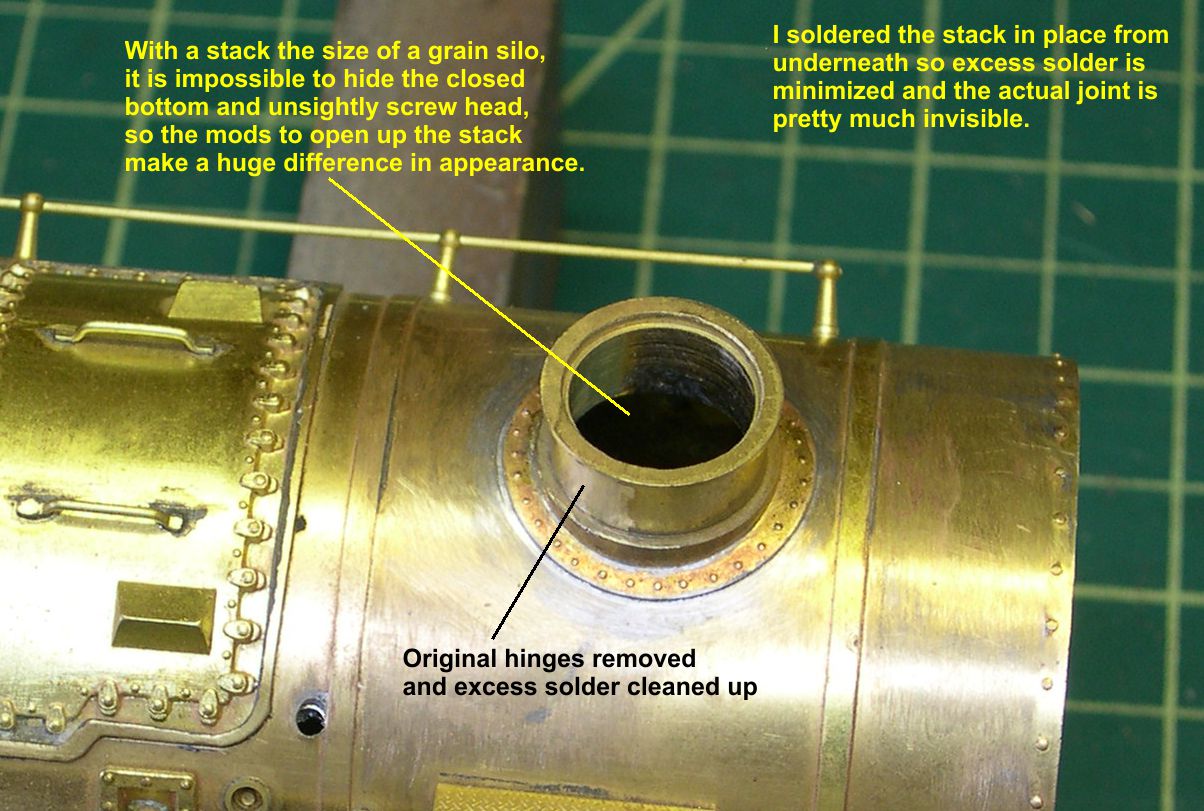
Note how easy it is to see into that huge hole. Sure couldn’t hide a screw in there! Also note that the original hinges have been removed and the excess solder cleaned up.
Photos 10-12 show various views of the finished flip top stack.
photo 10 ⤵
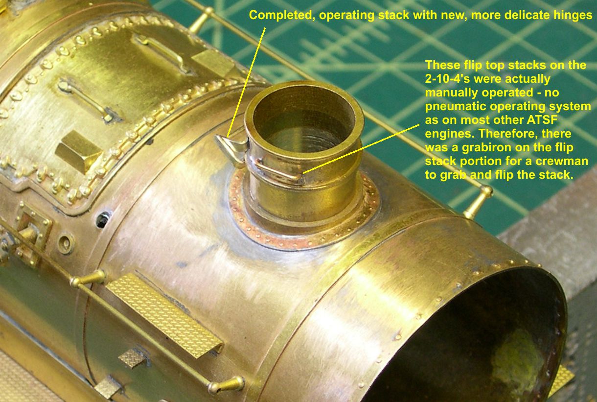
It is totally prototypical in being manually operated. The grabiron on the side of the flip top section was used to operate the stack. Most ATSF extender or flip up stacks were pneumatic (air) operated with a small cylinder and lever system next to the stack.
photo 11 ⤵
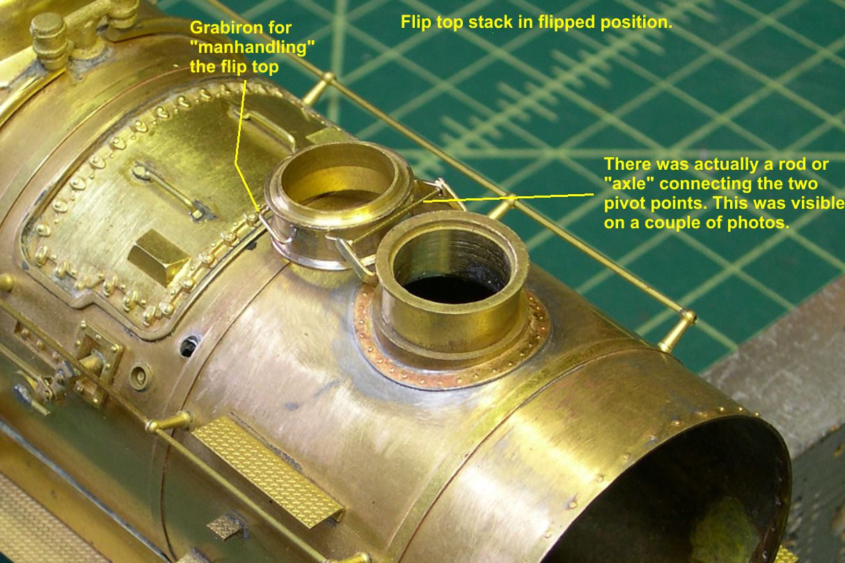
I do not know why such a system was not used on these 2-10-4’s. The angled grabiron is not a sloppy application by yours truly. Apparently, placing it at an angle like that, as opposed to pointing straight out to the side, gave some mechanical advantage for the manual operation.
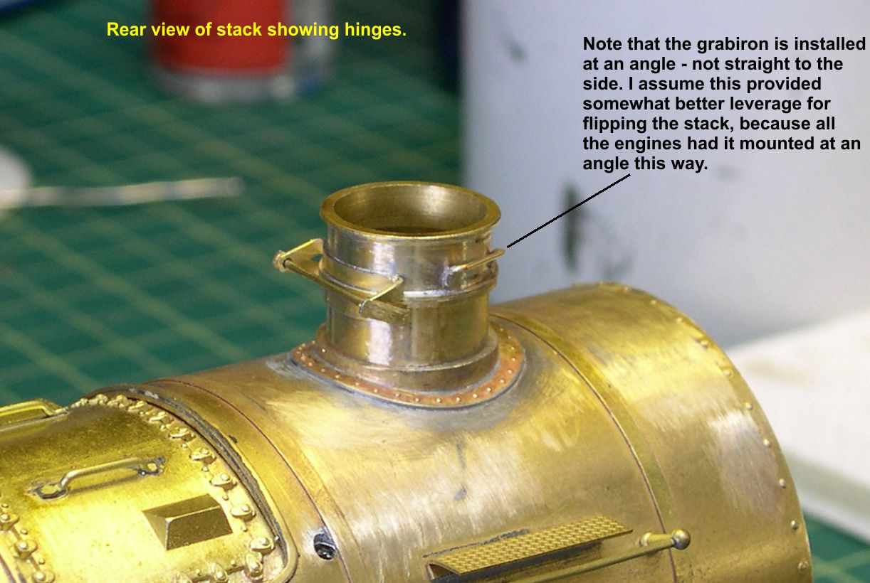
photo 12 ⤵
I also did not put any bolts on the ends of the grabirons, as I suspect they were welded rather than bolted in that position. None of the photos I have could conclusively prove or disprove that.
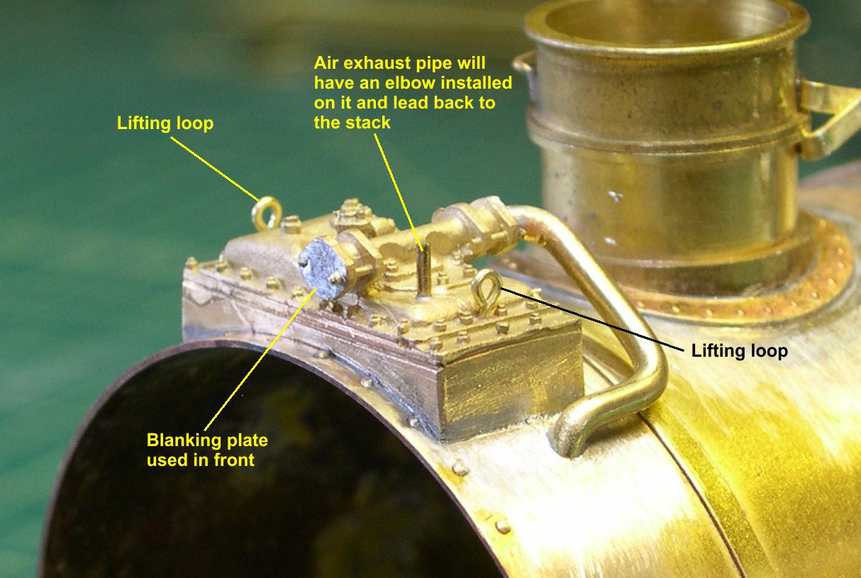
At this point, I moved on to the Worthington SA-6 feedwater heater. The PSC castings needed some cleanup and some holes drilled for various attachments. The inside of the castings are hollow, which makes it easy to drill holes clear through to the interior, then solder the attachments from underneath. Just to be sure I did not dislodge any of the pre-applied parts during subsequent soldering operations, I applied a blob of paint over each solder joint inside the castings. That will usually keep the joints from loosening up except under the most extreme conditions. The castings had lifting loops cast in, but some of them did not turn out OK, and they were in the wrong places for ATSF practice anyway. I just cut off the remnants of the loops and drilled new holes in the right places as shown in photo 13.
photo 13 ⤵
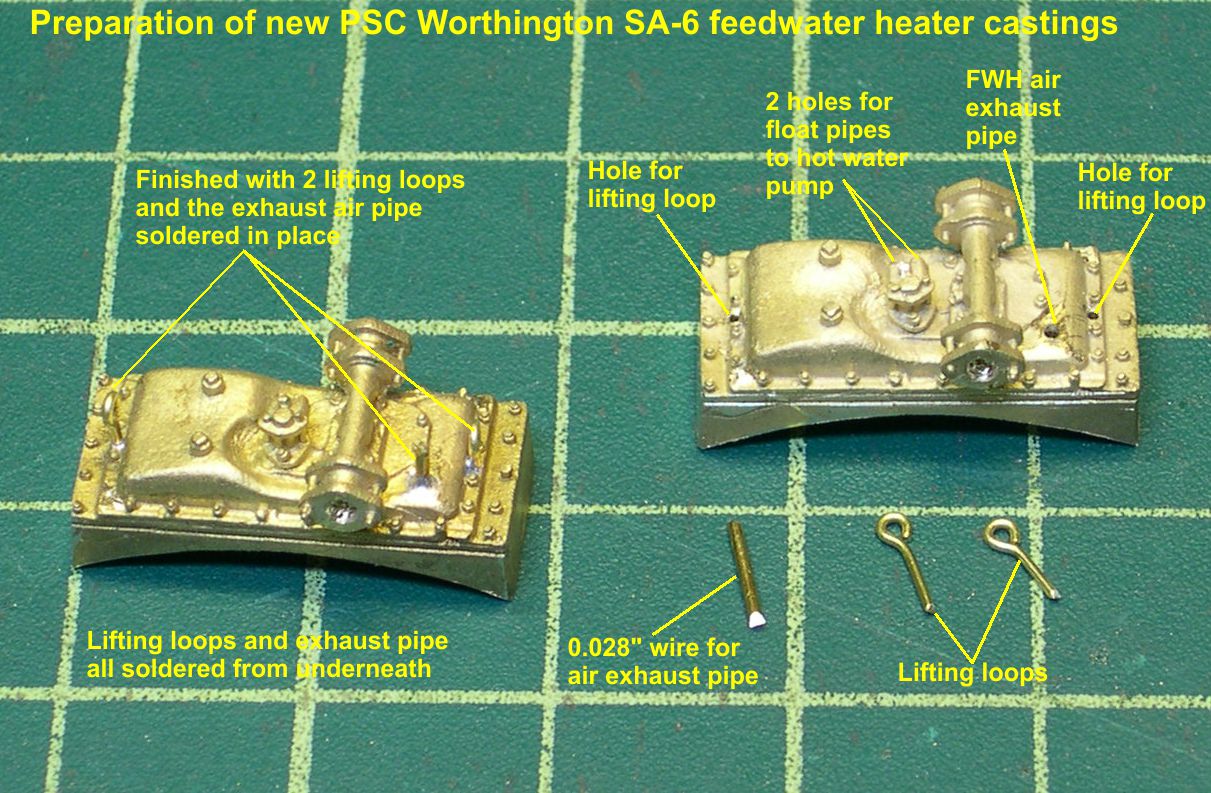
The castings also had a nice pipe with elbow cast on for the air exhaust pipe. Unfortunately, the elbow faced the wrong direction, so I had to cut it off as well and drill a hole for the new pipe. I also drilled out the large connection for the cold water pipe and the two small connections for the float pipes to the hot water pump. On the left in photo 13, is a completed FWH with the lifting loops and air exhaust pipe soldered into it.
Photo 14 shows the FWH soldered in place and the cold water pipe added.
photo 14 ⤵
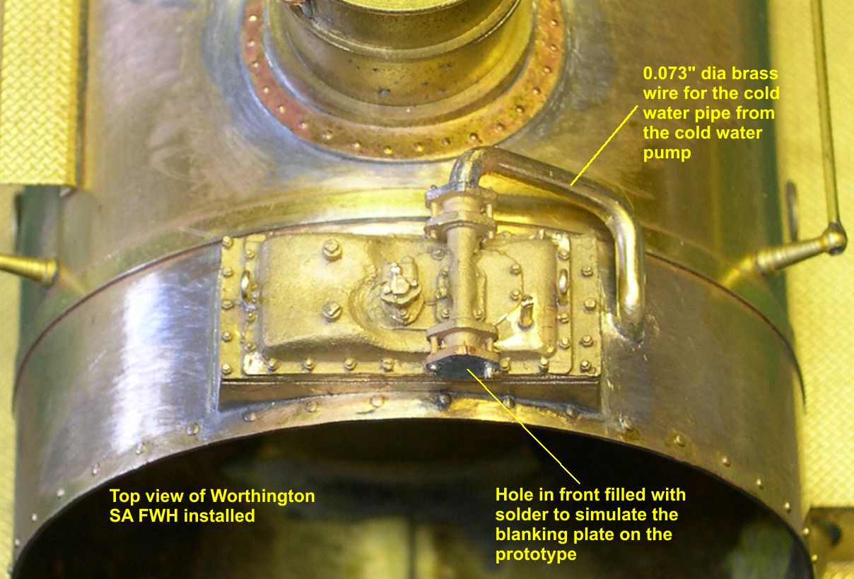
The lower end of the cold water pipe goes through a hole into the smokebox. I found that the easiest way to fit up this pipe was to start at the end going through the hole into the smokebox and do the bends to get it to fit the upper connection. Either way will work, of course. With this 0.073″ diameter cold water pipe successfully fitted and soldered, I filled the open end of the pipe on top of the FWH with solder and filed it smooth to look like the blank off flange used on the front end of that double ended fitting. You want to do this last, so you dont’t suffer any “sink” of the solder during later heavy soldering. The remaining soldering to the FWH will be too light to create a “sink” problem with this blank off. By the way, exactly fitting the FWH casting to the top of the smokebox requires a lot of patient filing and fitting. Do not get into too much of a hurry, as a nice fit is really essential for best looks. Photos 15 and 16 are views of the FWH from different angles so you can see the lifting loops, etc.
photo 15 ⤵
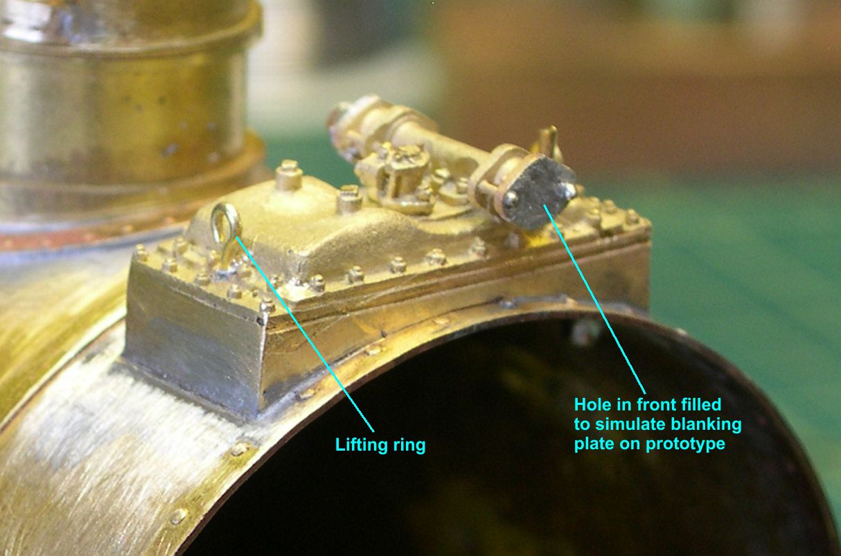
photo 16 ⤵