AT&SF Class 5001 Misc Details – Strainer
In this installment of the 5001 class saga, I add a number of miscellaneous details to the boiler. There are 10 photos attached showing these details. Starting with photo “Misc Details-1”, you can see the added air brake and signal pipes that run from the cab, under the firebox, and behind the right side appliances up to the front of the engine.
misc detail 1 ⤵
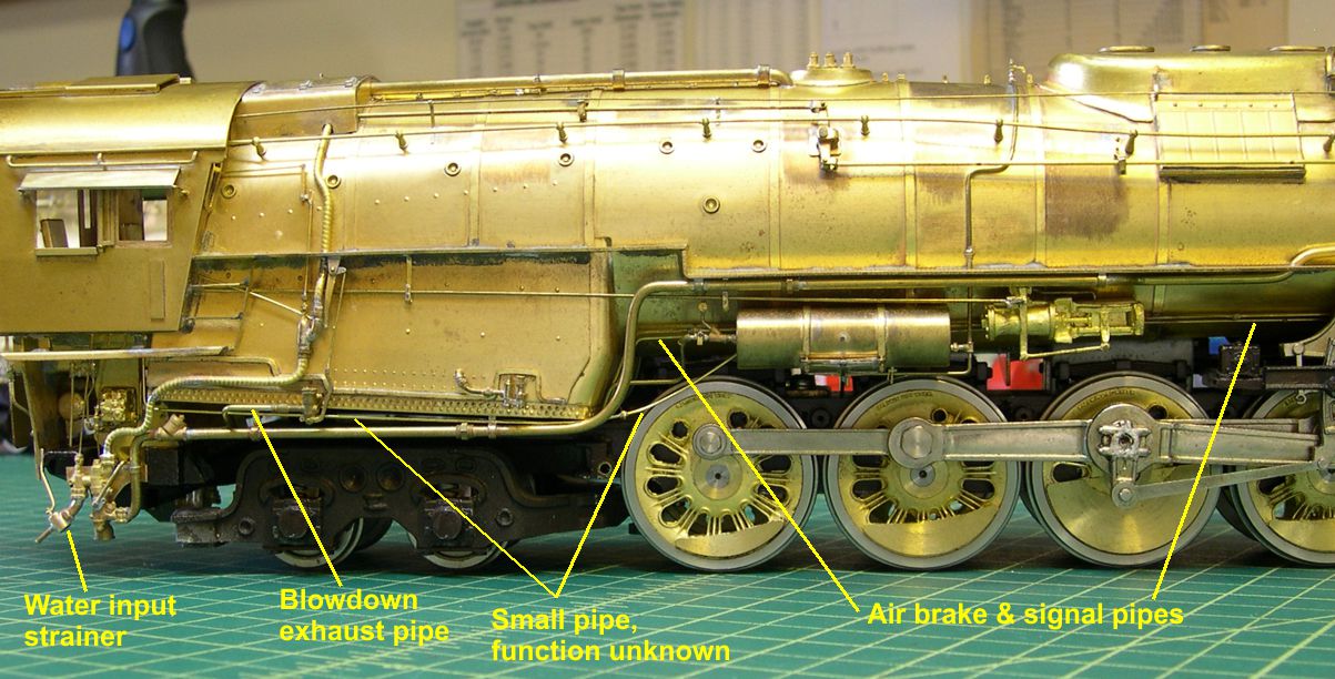
I had also forgotten a couple of pipes along the bottom of the firebox. One is the exhaust pipe for the right side blowdown valve. It runs back under the cab to a blowdown spreader between the rails. The other pipe is a fairly small one that runs from the bottom of the cab, along the side of the cold water pipe, then disappears behind the air tank. I do not have a clue as to what the purpose of this pipe is, but all the engines got it later in life, so it was not just an experiment. I had also forgotten to add the strainer just behind the injector. It does what the name implies – it strains debris of all kinds out of the tender water before that debris can be ingested by the injector. It is a common fitting behind injectors, but each railroad seems to have had its own design. Later, I will discuss how I made it.
Photo 2 is a closer view of those details.
misc detail 2 ⤵
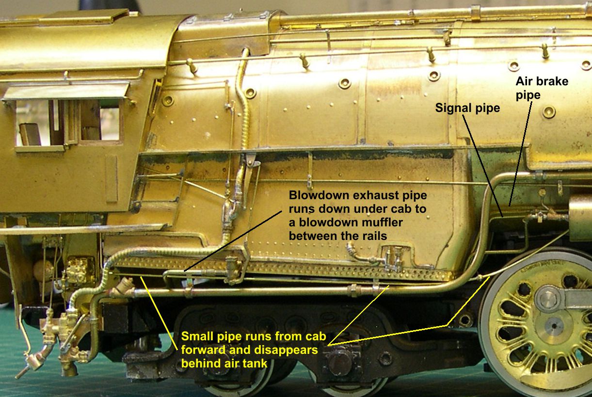
Photo 3 shows the front portion of the air brake and signal pipes.
misc detail 3 ⤵
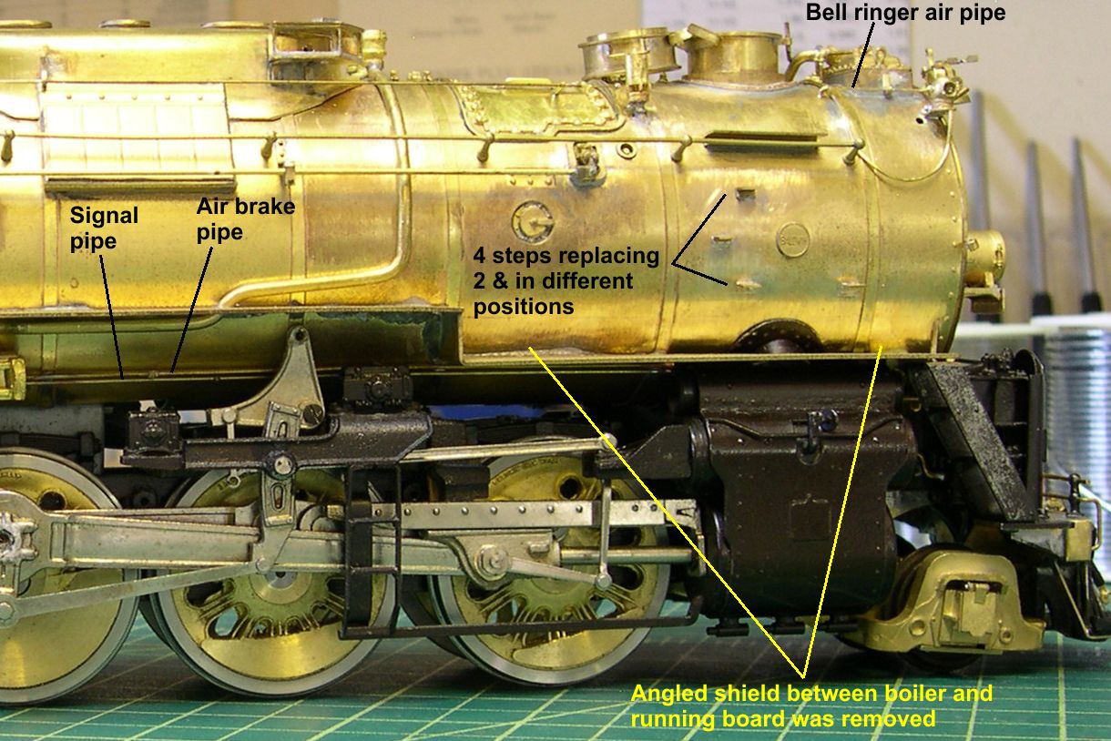
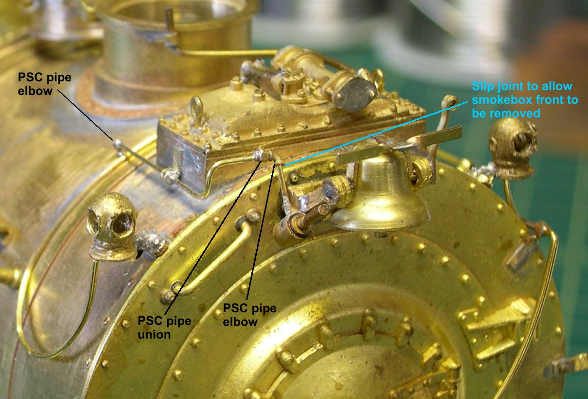
It also shows how I removed the angled shield that was installed at about a 45 degree angle between the boiler and the running board on the lower portion of the running board. Both 5001 and 5011 class 2-10-4s had that shield as delivered, but they were all removed by the late 40s to early 50s. The small boiler steps around the builder’s plate had to be increased from just two up to the correct 4, and all the positions had to be moved as well. The USH model had two steps, but the 5011 class it represents had 3, and the 5001 class had 4. Up at the top of the boiler, I installed the piping for the air operated bell ringer. That piping had several pipe elbows and unions in it that add interest and also make it possible to have a convenient slip joint in the pipe that allows one to remove the smokebox front. That is pointed out in photos 4 and 5.
misc detail 4 ⤵

misc detail 5 ⤵
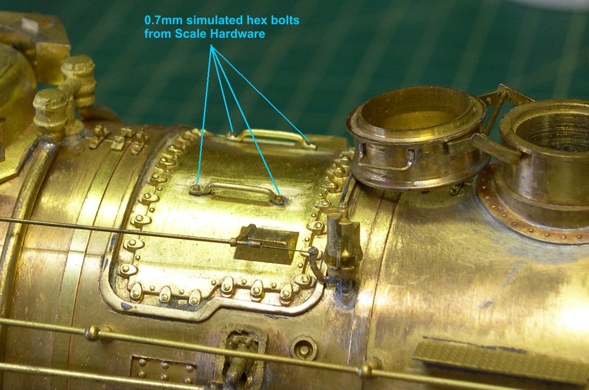
Also in photo 4 you can see a small pipe that exits the smokebox at the end of the running board, drops below the running board, and then turns to the rear and disappears. This is another “purpose unknown” item. In photo 6, I show where I added the simulated bolts to the ends of the grabirons on the superheater cover.
misc detail 6 ⤵
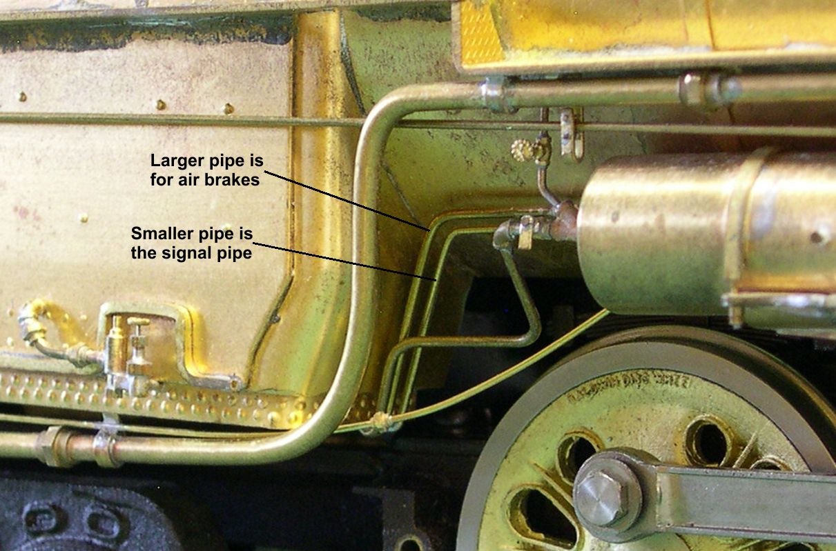
The 7th photo is a close up of the area at the front of the firebox so you can see the difference in size between the air brake and signal pipes.
misc detail 7 ⤵
I have set aside 3 photos to show the construction of the strainer behind the injector. Photo “Strainer-1” shows the parts being put together for the two strainers, one for each engine.
strainer 1 ⤵
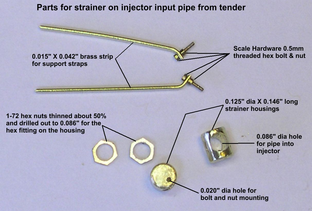
The main body of the strainer is a piece of 1/8″ brass rod cut to a length of 0.146″. I rounded the edges slightly to more accurately portray the prototype. Then I drilled a 0.086″ hole to allow the piece to be slipped onto the intake pipe of the injector. Another hole, 0.020″ dia, was drilled in the top to take the bolt that holds the strainer to a strap steel brace. There was a hex fitting on one end of the strainer. I drilled out a pair of 1-72 hex nuts and filed them thinner to represent that fitting. It was slipped onto the input pipe first, then the main strainer body was slipped on and both were soldered in place. The strap steel brace that holds the strainer to the frame was built up using 0.015″ X 0.042″ strip brass, a 0.5mm threaded brass hex bolt, and a 0.5mm hex nut. The nut and bolt were inserted through a hole in the strip brass and tightened. On the prototype, the height of the strainer was adjusted using this bolt, so it was not screwed all the way into the strainer as you can see in the finished photos, numbers 2 and 3.
strainer 2 ⤵
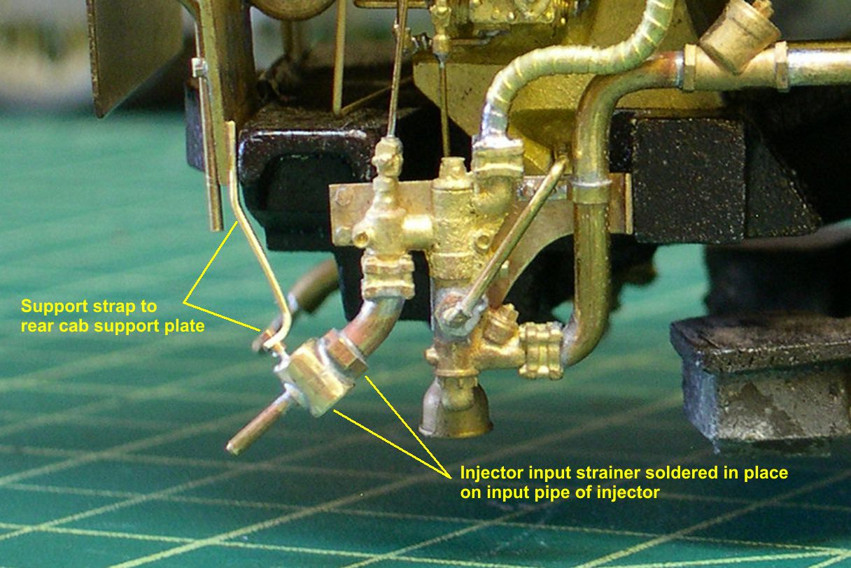
strainer 3 ⤵

After shaping the brace to attach to the rear cab support plate, I soldered the strap to the plate and the bolt into the hole in the top of the strainer.
Every time I examine the photos, I discover more things to add, so there are still a few details to go on the boiler before I get around to the backhead detailing.