AT&SF Class 5001 Turret Hatches – Number Boards
This segment has taken a little longer to complete due to the difficulty of the two items covered. The tasks are shown in the 23 photos attached. On the surface of it, they are fairly simple items, install new hatch covers on the steam turret ahead of the cab and install the number boards just ahead of the sand dome. However, a lot of thought and time consuming work had to go into both. The finished items look pretty simple, but getting there was not.
The first step in doing the turret hatches is to cut out the hatches themselves from 0.010″ brass sheet stock. After getting them filed down to exact size with smooth edges, etc., it is necessary to curve them slightly to match the curve of the turret. I have ordered a roller type curving machine from Micromark because I am getting tired of figuring out innovative ways to curve sheet brass, but it has not arrived as yet, so I had to get creative on these hatches. In the photo “Turret Hatches-1”, I show the setup I used.
turret hatches 1 ⤵
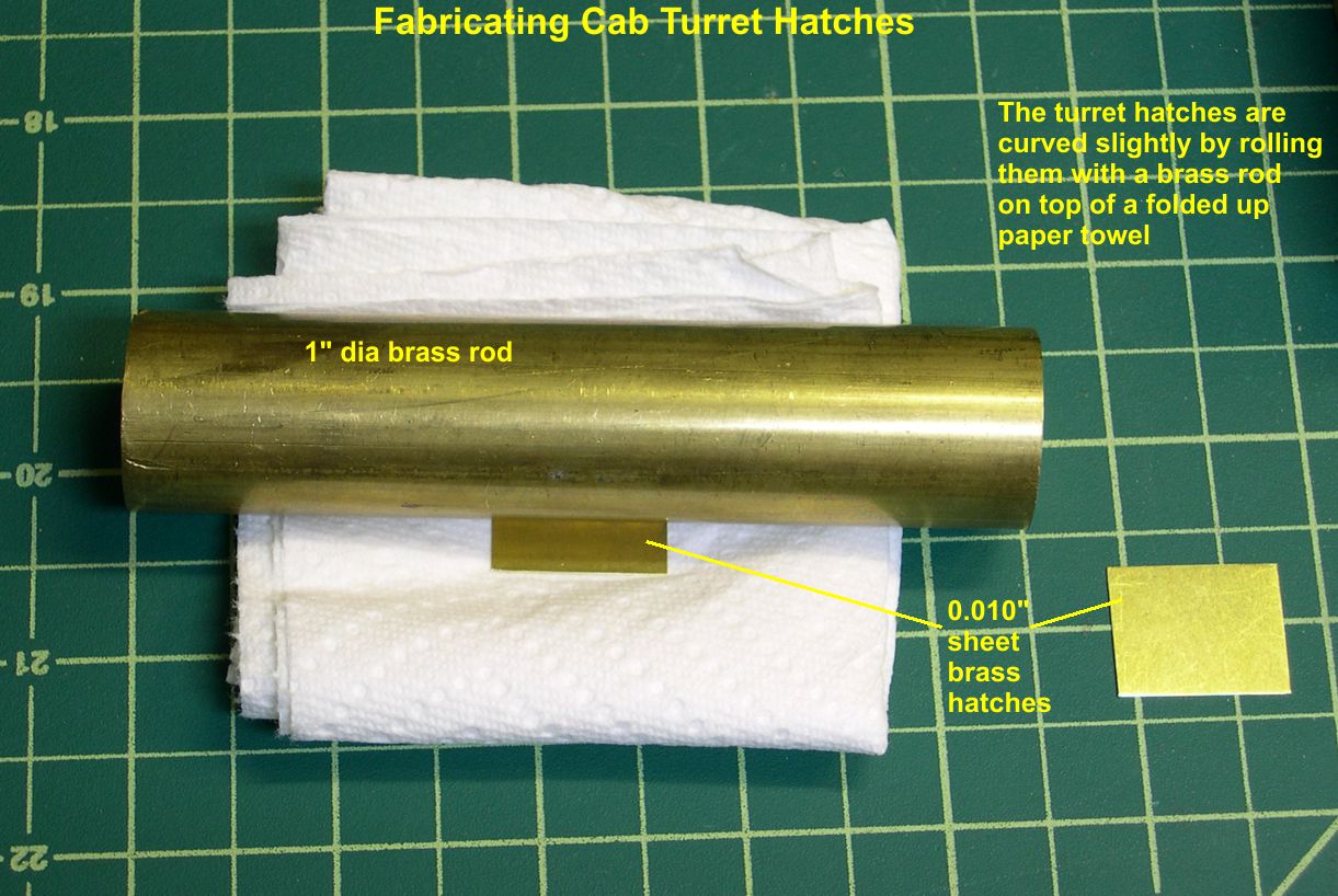
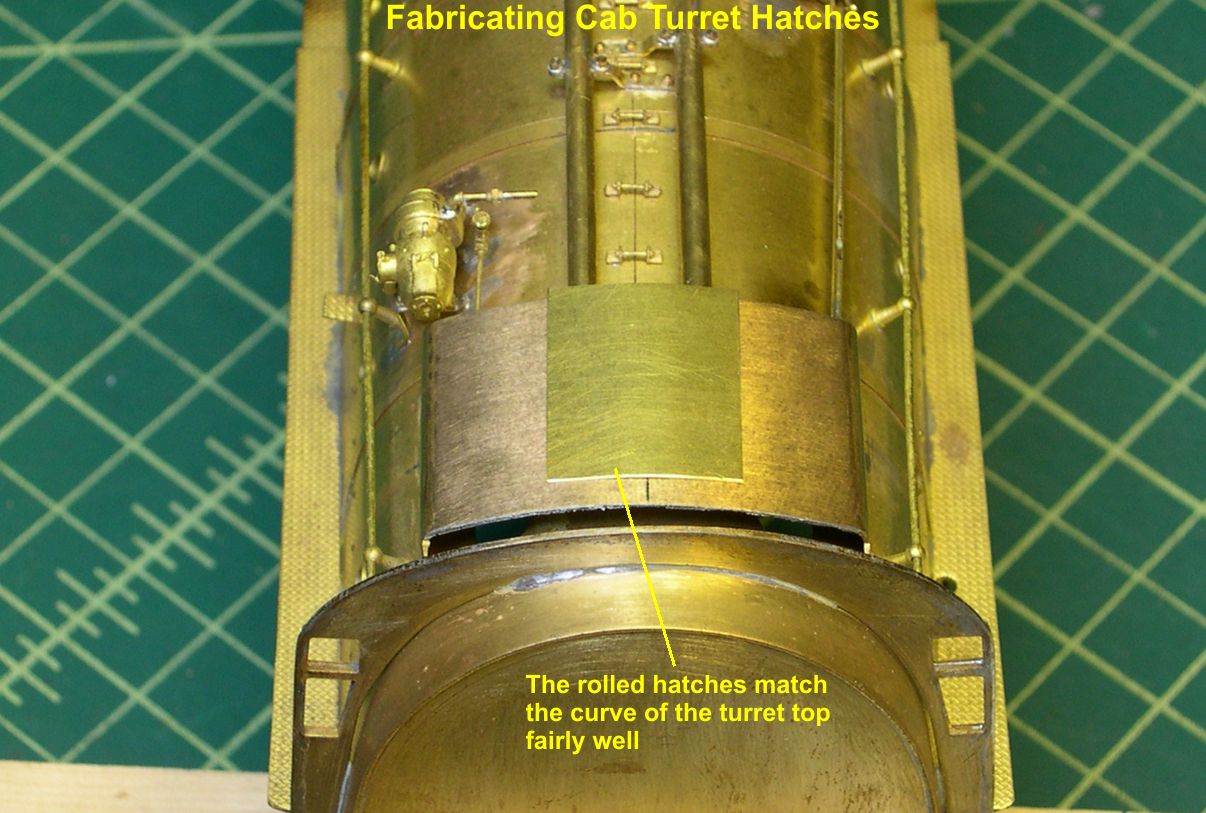
I folded up a paper towel so it was pretty thick and would “give” a fair amount when pressed. Then I placed the hatch on the towel and rolled a 1″ diameter brass rod across it repeatedly while pressing down hard. The give of the towel allows the brass sheet to bend slightly in a controlled manner. You just have to roll and test until you get the right curvature to match the turret as seen in photo 2.
turret hatches 2 ⤵
Then I soldered the hatches in place as seen in photo 3.
turret hatches 3 ⤵
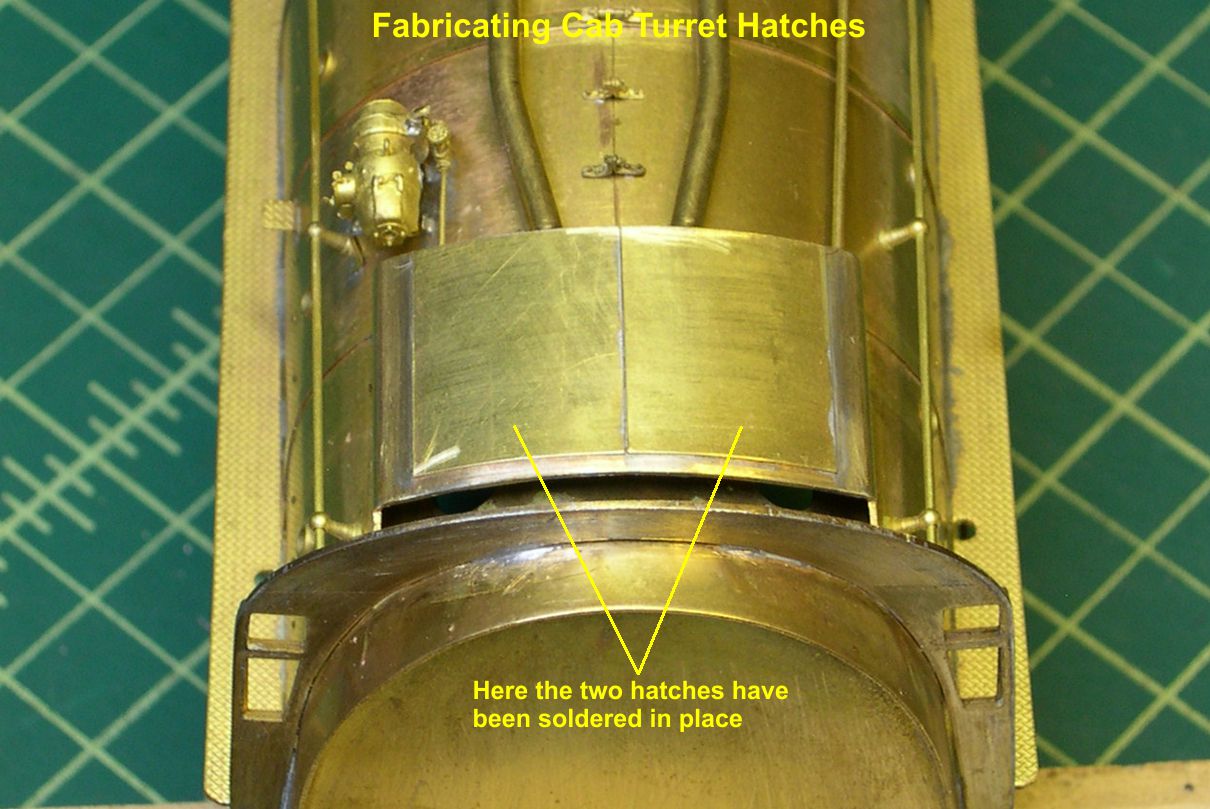
Note that using two separate pieces gives a much more realistic parting line between the two hatches than simply scribing a line on a single piece would.
Now comes the hard part – making a dozen small hinges that look exactly the same. Any variation in shape or size will stand out like a sore thumb. In the past, I have tried making such parts one at a time and found it to be extremely difficult to get just a few matched perfectly, let alone a dozen. More and more, I find it much easier to just solder all the parts together, shape them as a solid block, then unsolder them. That gives a dozen precisely the same hinges with minor effort. Photo 4 shows the 12 pieces of 0.010″ X 0.060″ brass hinges that were soldered together and shaped as a single block.
turret hatches 4 ⤵
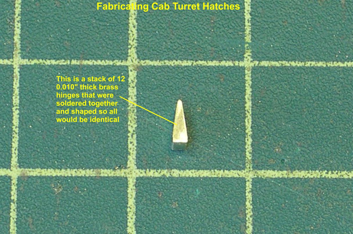
Photo 5 shows the result, 12 perfectly matched hinge pieces.
turret hatches 5 ⤵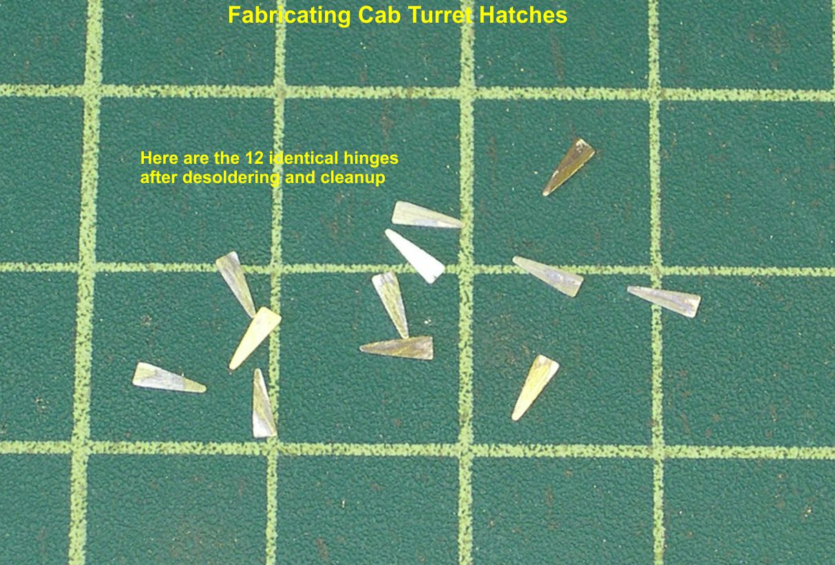
Slight filing to clean off any excess solder is all the clean up required. In photo 6 you can see the remaining pieces required for the hinges.
turret hatches 6 ⤵
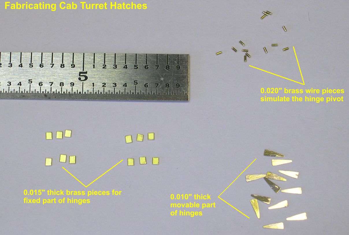
The small square pieces are the fixed part of the hinge that goes on the turret itself, the tapered pieces are the moveable parts, and the small bits of wire simulate the pivot of the hinge between the two other parts. I included the steel rule in the photo so you can get a feel for how small all these parts really are.
Photo 7 is a close up of the completed hinges after all the parts were soldered in place and rivets added.
turret hatches 7 ⤵

I used Scale Hardware 0.4mm and 0.5mm simulated rivets. The latch between the two hatches was built up the same way as the hinges, although there was no real shaping to do, so soldering the parts together was unnecessary. Drilling all those little holes (#79) and soldering all those tiny rivets in place was not a quick job. I kind of had to flog myself into continuing at times. In photo 8, I have tried to get a good shot of the little loop for fastening the latch, but it’s hard to convince the camera to focus up close on such a little target.
turret hatches 8 ⤵
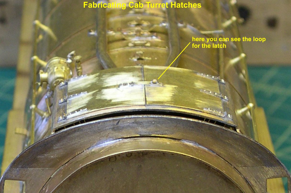
The loop itself is just a piece of 0.015″ wire inserted in two holes and soldered in place.
Having completed the tedious job of doing the hatch covers and hinges, I next took on the more difficult job of doing the number boards. Now usually the number boards on a Santa Fe engine are pretty straight forward, as PSC does some nice castings for them. However, on the large engines built after 1937, the 2-10-4s and 4-8-4’s, the Santa Fe decided to modify their number boards to fit the curve on the front of the large sand dome and mount them on brackets to the front of the dome. No one makes a casting for those, so I had to modify the earlier number board castings to represent the new ones. This is a tough job just short of scratch building them. In the photo “No Brds-1”, I have shown what the PSC castings look like after removal of the casting sprues, removal of the hinge and grabiron detail on the tops of the castings, and clean up of any flash.
number boards 1 ⤵
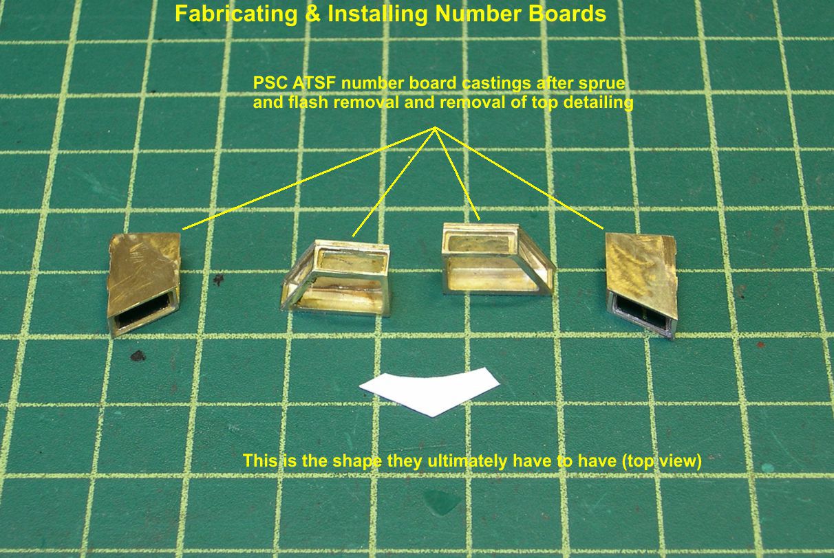
Sitting in front of the castings is a template I used for shaping the backsides of the number boards. I had to cut and fit around the front corner of the sand dome until I got the right shape to match that corner. Note that the bottoms of the number boards are open to facilitate the casting process.
The first thing to do in making the new number boards is to solder bottoms on them. They need bottoms anyway, and the bottoms will improve their overall strength for the rough shaping to follow. In photo 2, I show the castings soldered to 0.016″ brass strip stock.
number boards 2 ⤵
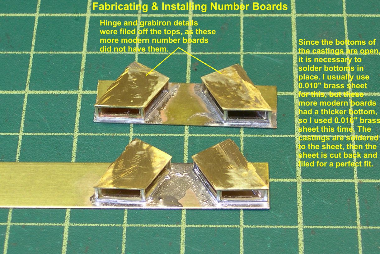
I normally use 0.010″ for the bottoms, but these more modern boards had thicker bottoms, so I elected to use thicker brass. I do not cut and fit the bottoms ahead of time. It is easier and more accurate to solder first, then cut the bottoms back to the casting and file them smooth to a perfect fit. You can see how nicely they finish up that way in photo 3.
number boards 3 ⤵
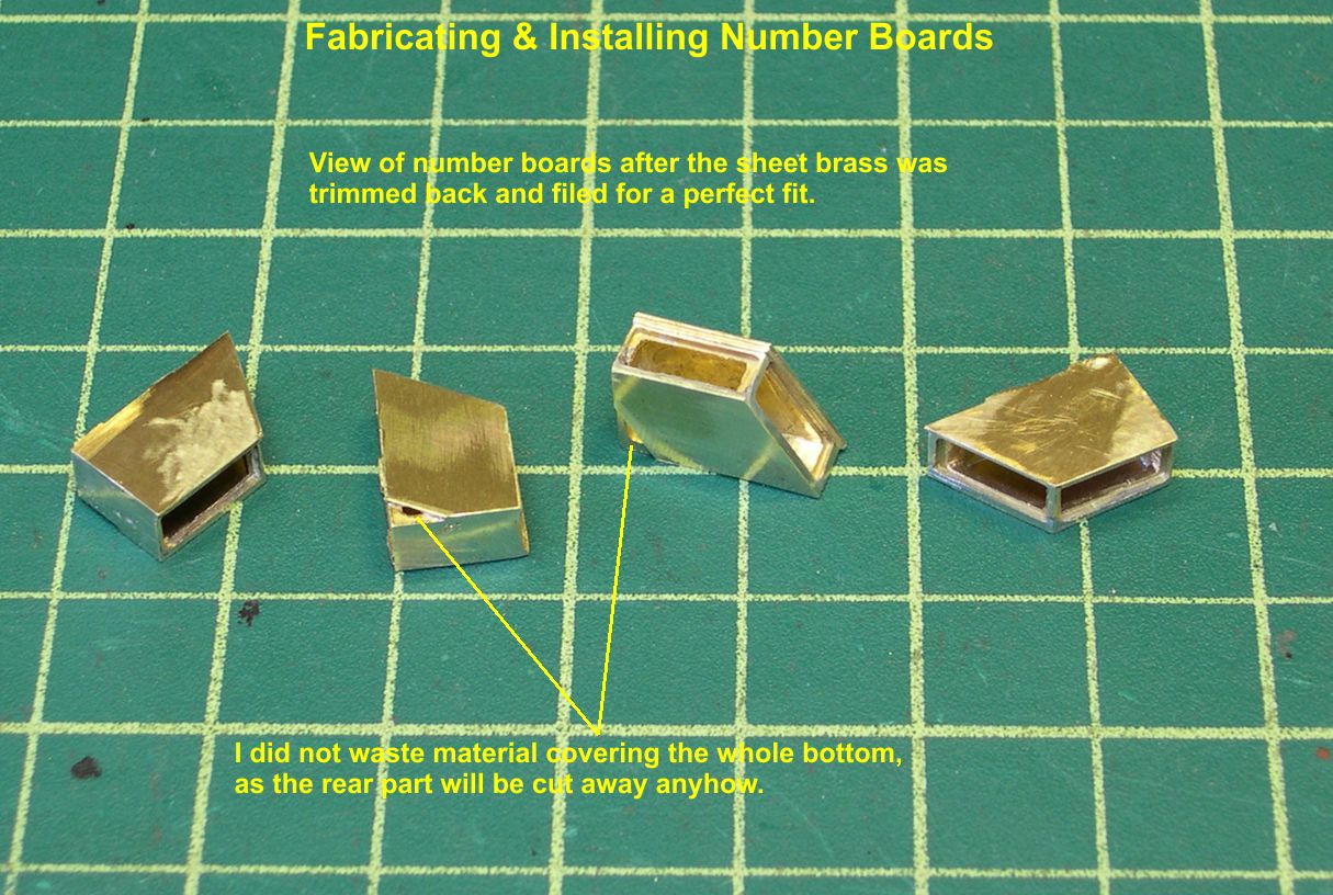
In that photo, I have pointed out that I did not try to cover the whole bottom. The rear of the number board is going to be cut away anyway, so why waste even more material where it is going to be removed?
After installing the bottoms, I used the template in photo 1 to mark the tops of the castings and removed the rear portions by sawing followed by some judicious Dremel work and finish filing. The result is shown in photo 4.
number boards 4 ⤵
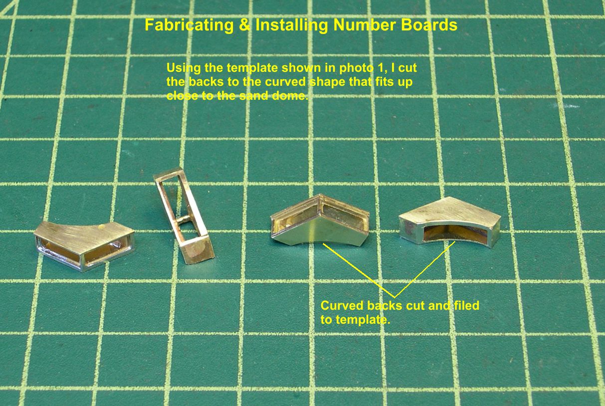
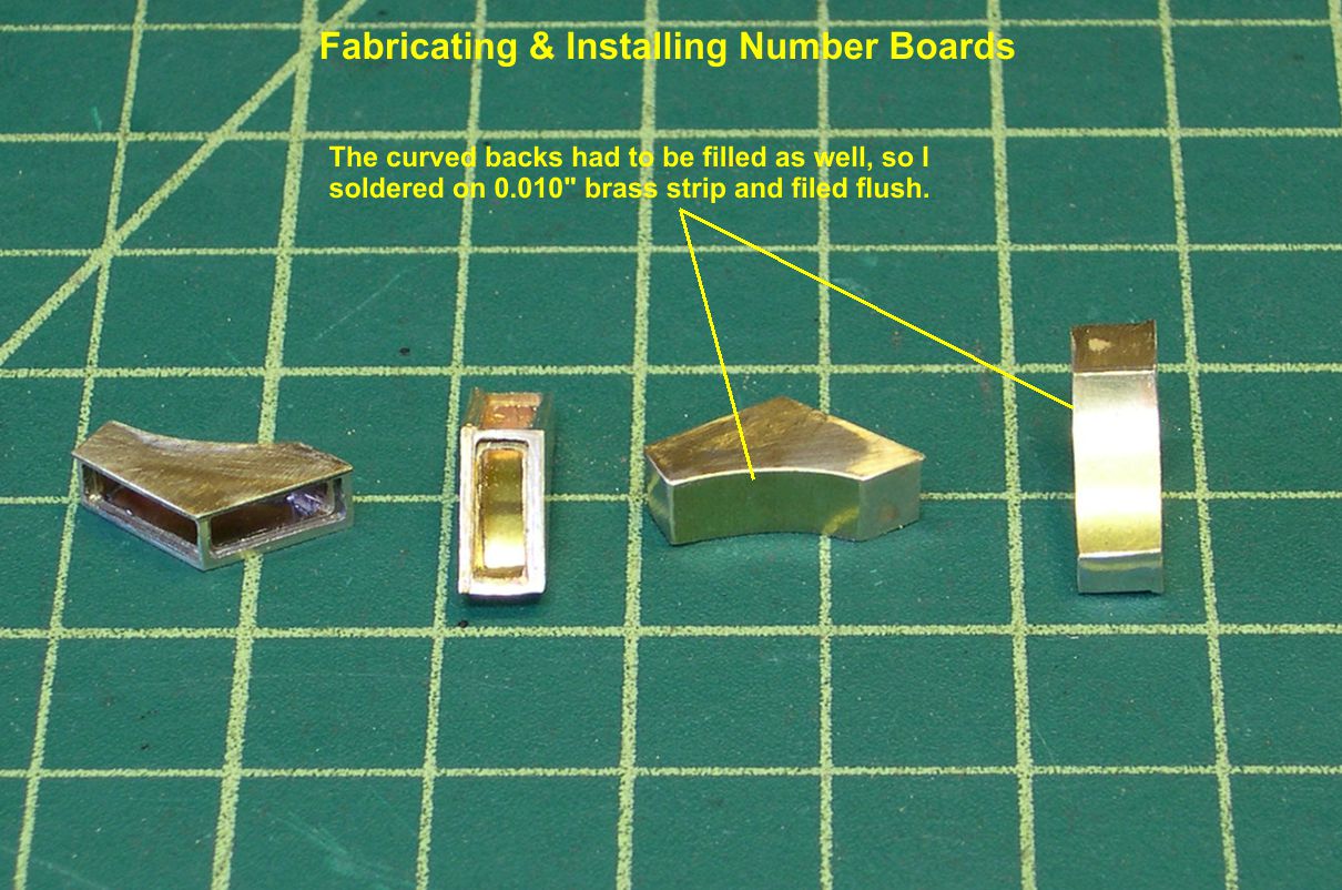
The backs have to be closed of course, so I soldered 0.010″ brass strip onto the curved backs and filed it flush with the casting. The finished curved backs are shown in photo 5.
number boards 5 ⤵
These newer boards had a small hatch on top that allowed access to the interior. I simulated that with a piece of 0.032″ brass strip as seen in photo 6.
number boards 6 ⤵

Also in photo 6, you can see the hole drilled in the back on each number board for the wiring to come later.
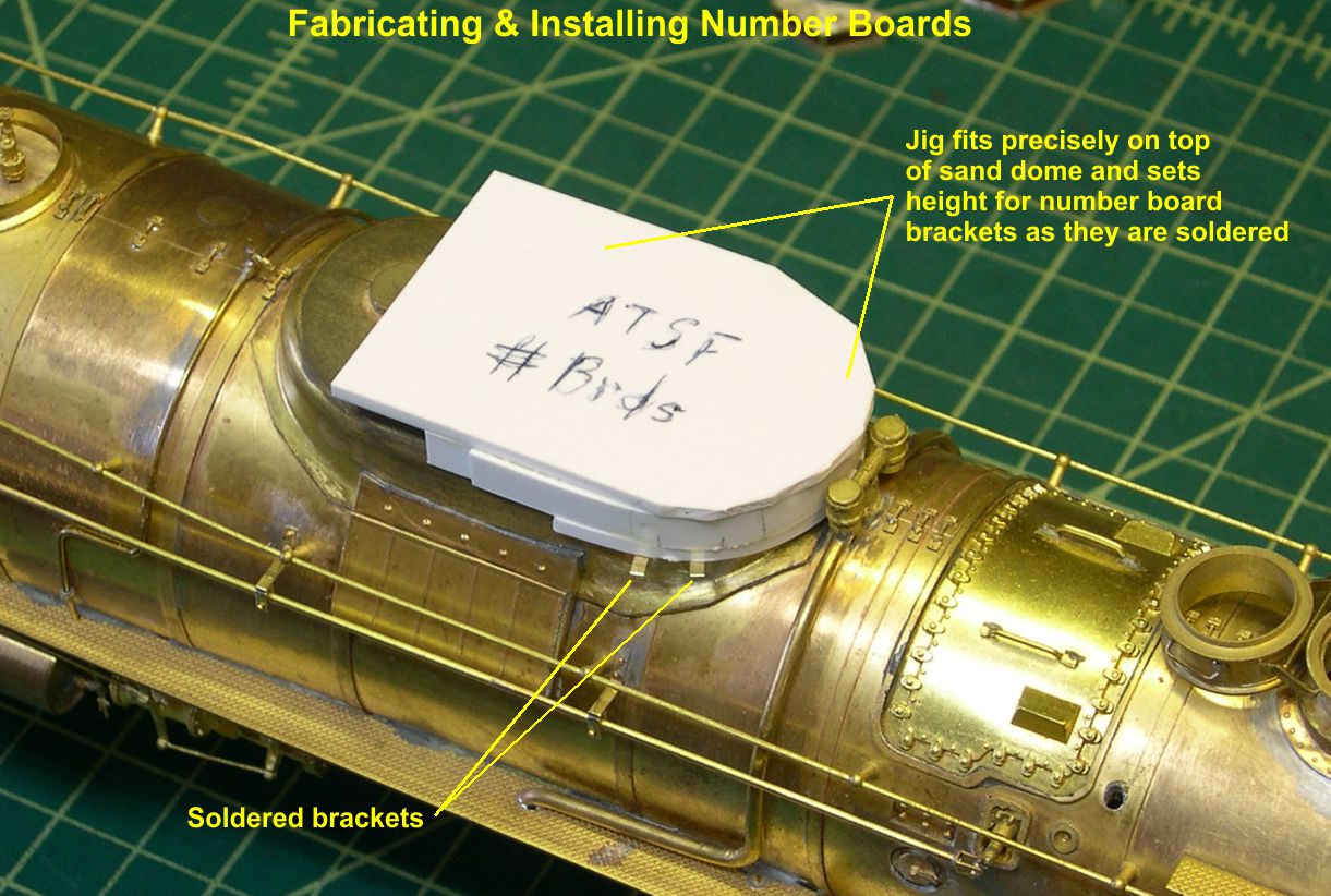
Now comes the REALLY hard part. How do you accurately position and solder those completed number boards to the sloping, curved corners of the sand dome? It took me quite a while to come up with a way to do it. First of all, the boards themselves do not touch the sand dome at all. They were mounted on a pair of simple angle brackets apparently welded to the sand dome, as I could not see any rivets or bolts in a really good close up photo. I finally decided I had to make up a fairly complex jig to do the job. I built it up out of styrene, and used strips of styrene internally to basically lock the jig to the top of the dome. Photos 7, 8, and 9 show details of the jig and how it is used to position the two brackets that hold each number board.
number boards 7 ⤵
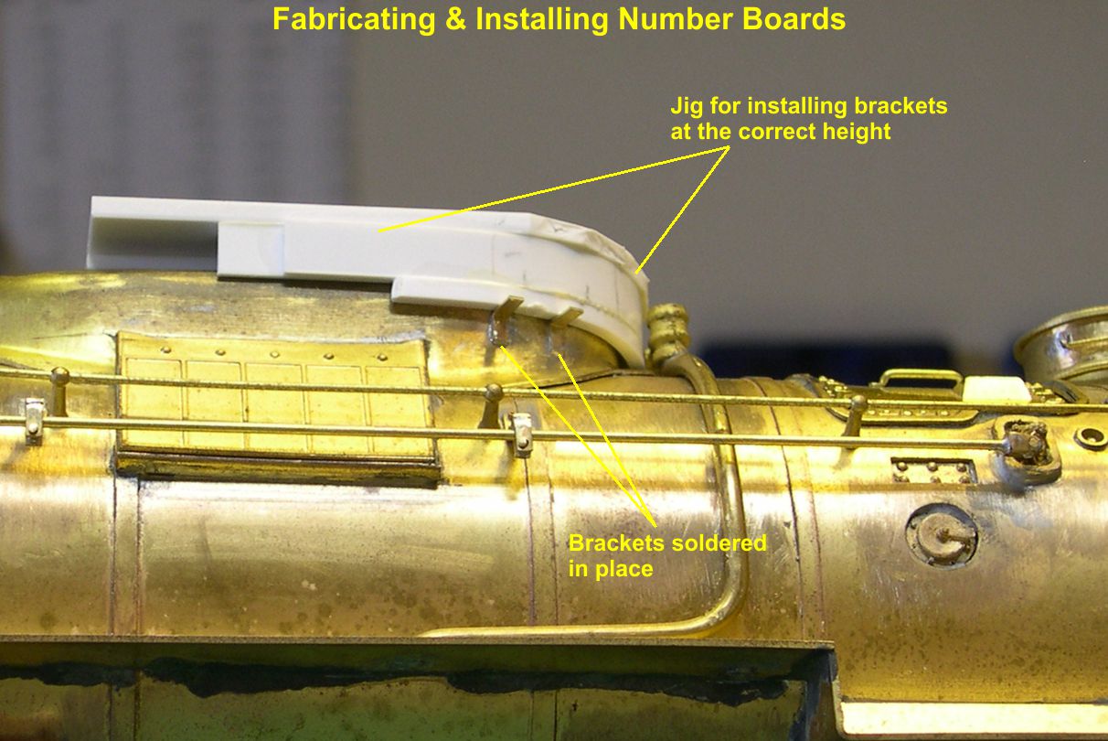
number boards 8 ⤵
number boards 9 ⤵
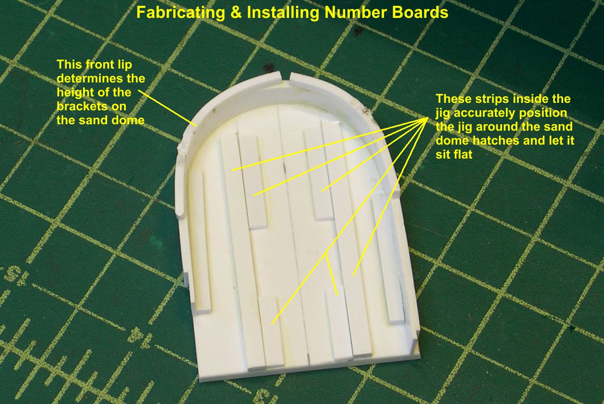
The brackets are made of 0.016″ brass strip. I used a light clamp to make sure the jig did not move while I soldered the brackets in place. As you can see in photo 8, I have marked the jig for future use on the same type of number boards. I sure do not want to re-invent the wheel each time. Once is quite enough, thank you.
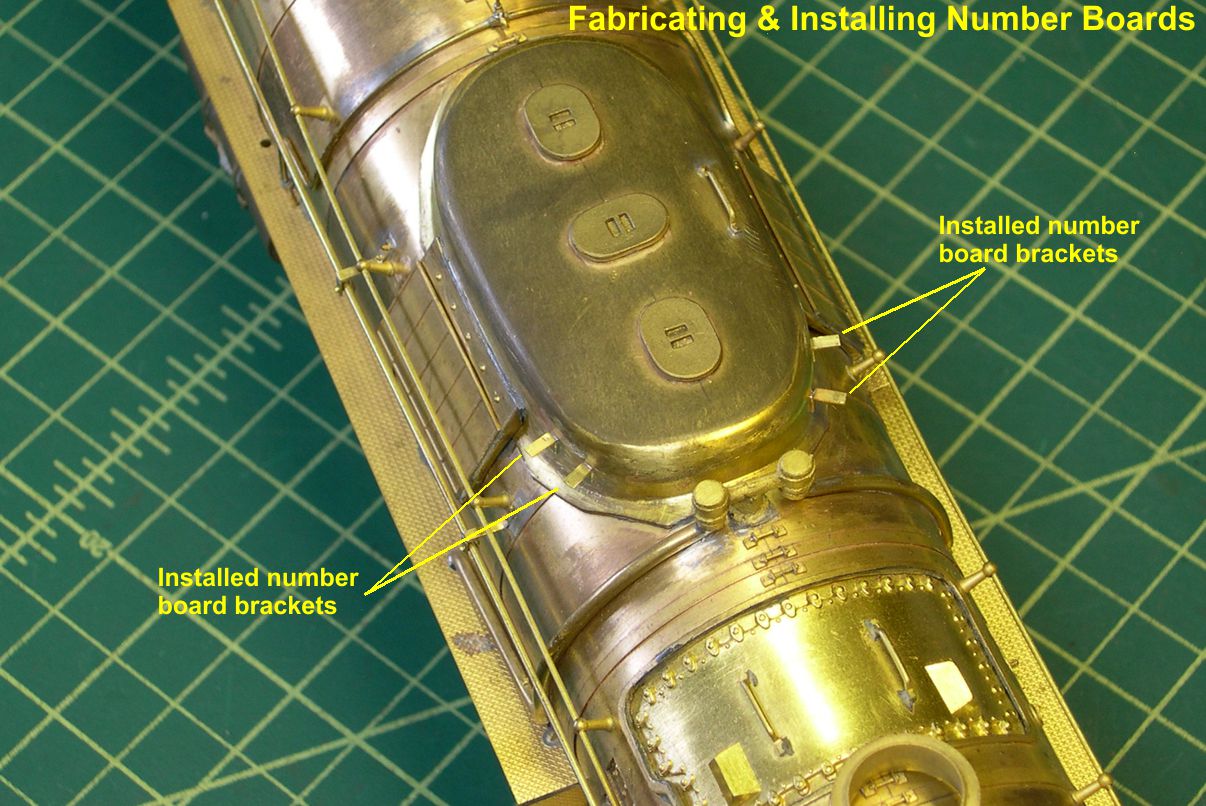
Photo 10 shows one of the models with the brackets installed ready for the number boards to be soldered in place.
number boards 10 ⤵
As mentioned before, the number boards did not actually touch the sand dome, so you cannot just slap them up on the brackets and solder them in place against the dome. You need a spacer to move them out slightly and make certain each one is the same distance from the dome. I just folded up a strip of cardstock to the right thickness and used is as my spacer. You can see how that works in photo 11.
number boards 11 ⤵
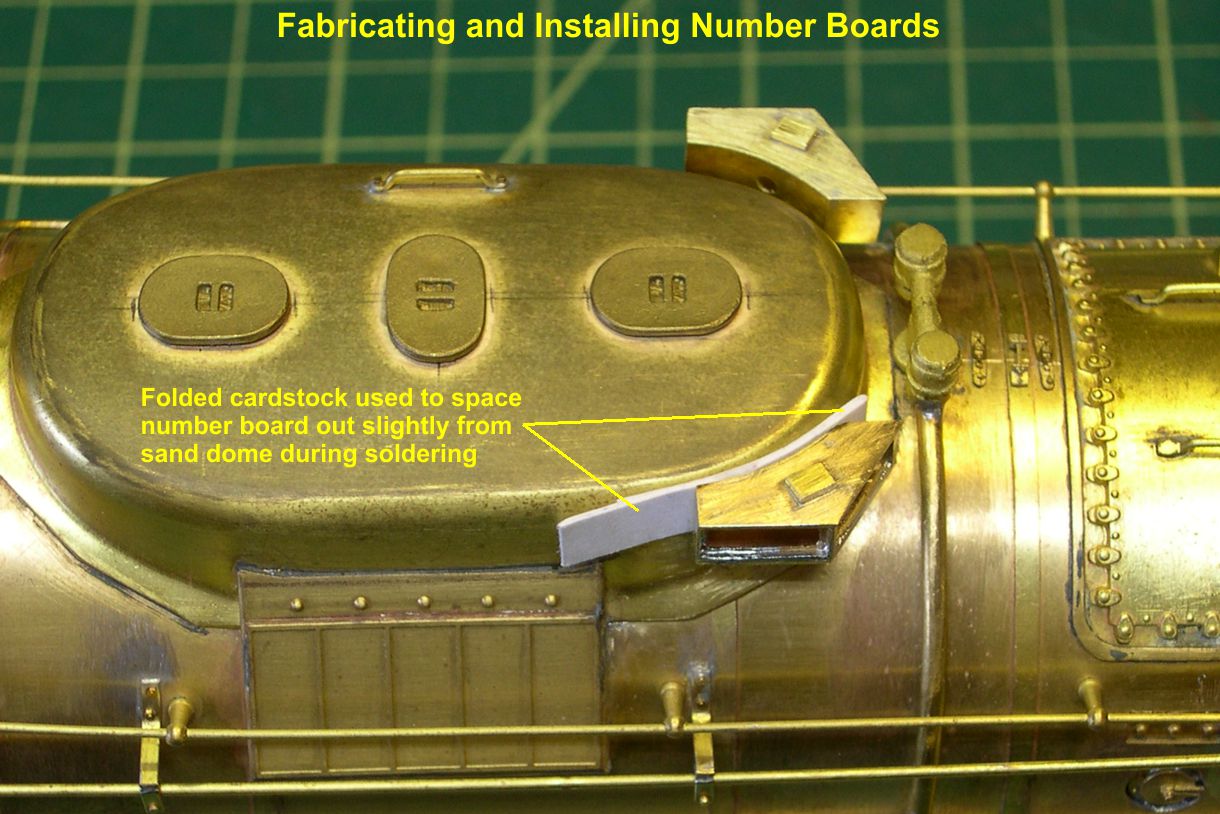
The thin cardstock is nice, as it is very flexible and forms to the shapes involved very easily. In photo 12, you can see how the number boards are actually standing out from the sand dome.
number boards 12 ⤵

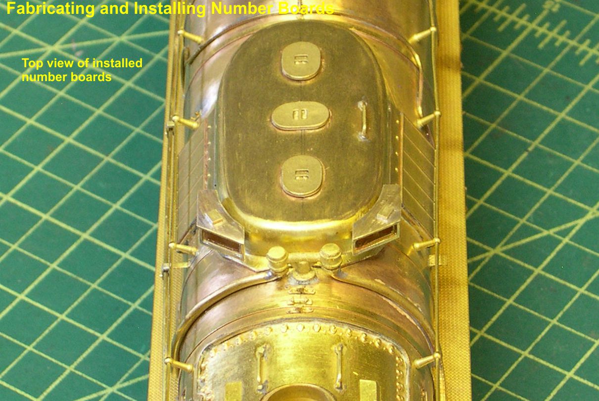
Photos 13, 14, and 15 are different views of the completed number boards.
number boards 13 ⤵
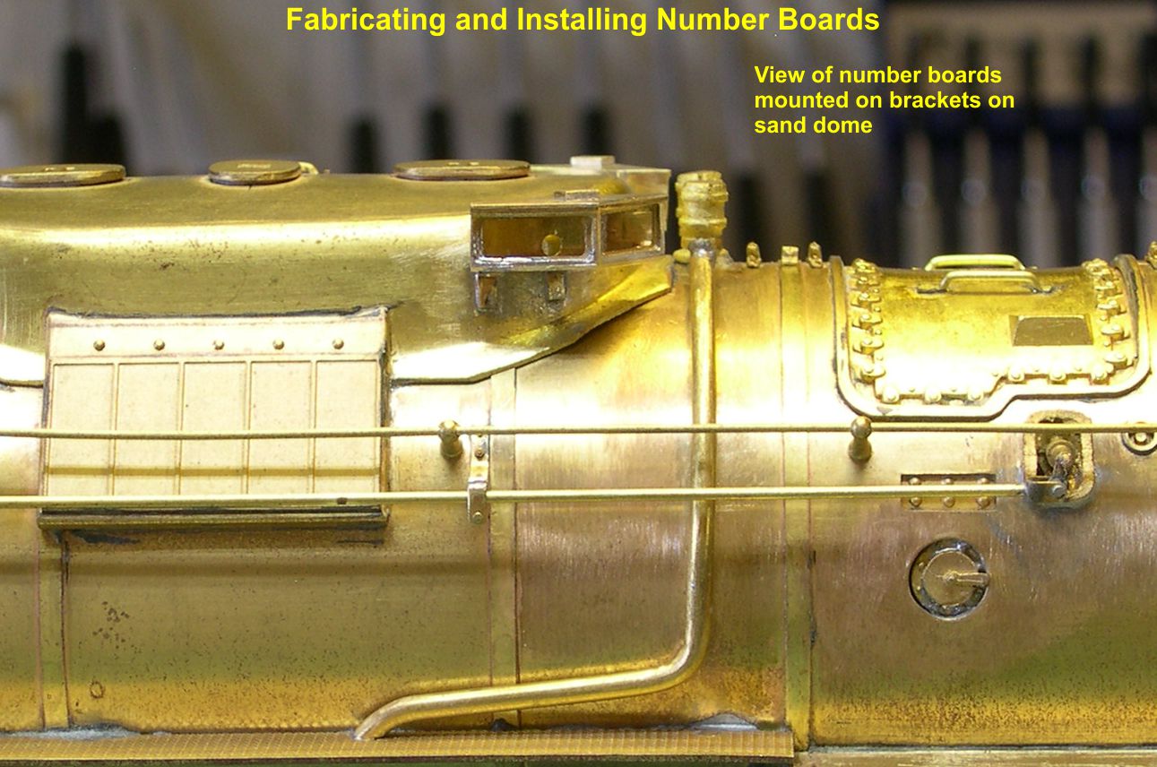
number boards 14 ⤵
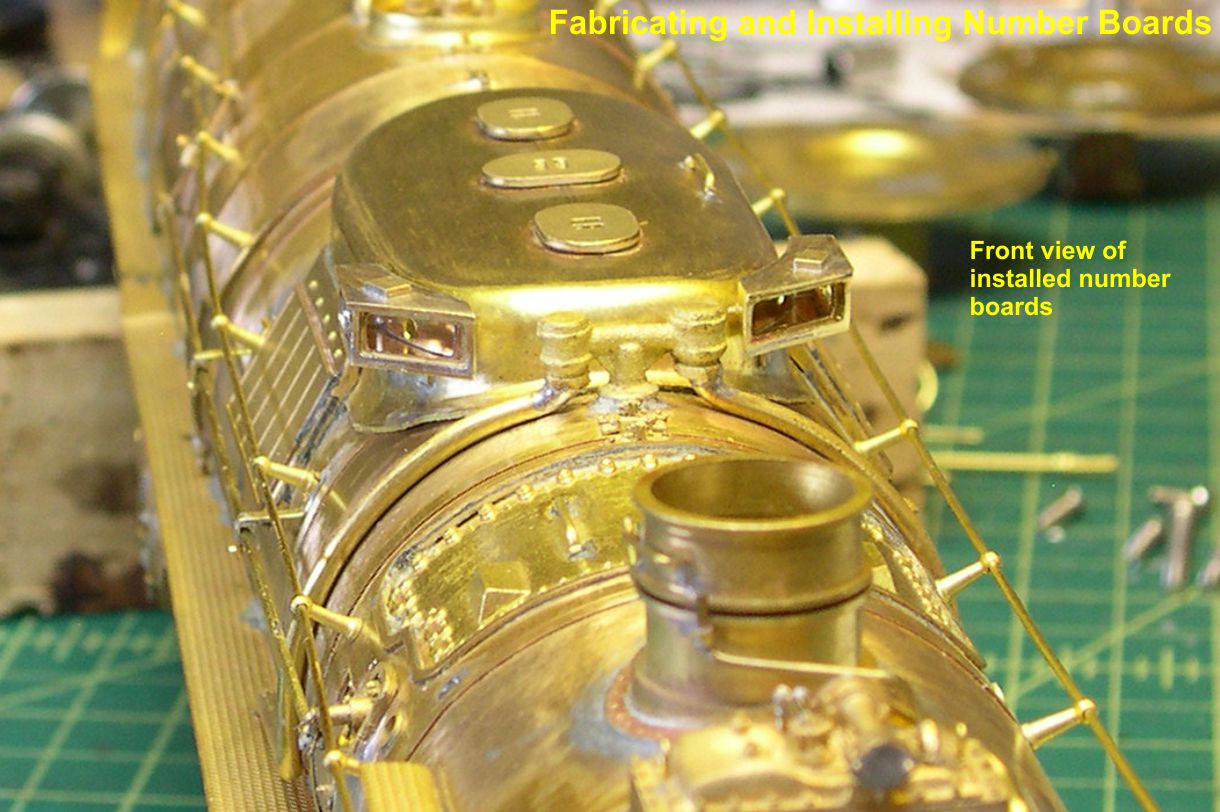
number boards 15 ⤵
With these two monster jobs completed, I am ready to go on to a lot of much simpler things like installing electrical conduit, class lights, whistle, and bell cord. Sounds like a vacation after this stuff.