AT&SF Class 5001 Westinghouse Distributing Valves – Injector
This installment is devoted to the Westinghouse distributing valve, its equalizing reservoir, and the injector. The injector is nearly a model unto itself. If you were expecting a casting soldered to two pipes, guess again. There is a LOT of work involved making a correct injector installation. There are 13 photos attached to this email showing how to do these two items.
The Westinghouse distributing valve needs to be done first, as it and the equalizing reservoir sit behind some of the other plumbing. These engines used the larger, later type 8 distributing valve, which PSC makes a casting for. A small reservoir tank is cast integral with the valve, which is usually great, but in this case, there is no room for it. The large support casting under the cab and behind the firebox on the original USH model is not totally correct. It sits a bit too far out to the side, but it is also an integral part of the frame to boiler mounting system, so moving it is not a good option. Fortunately, the position of the distributing valve is right square in the middle of the recess in that support. By cutting off the tank, I could position the valve exactly where it should be. The tank generally does not show on these big engines anyway, so no real loss. In this case, soldering to the large support would have been messy, so I chose to mount the valve with a screw from the back side. In photo “Distr Valve-1”, you can see how I prepared the valves for mounting by drilling and tapping a 1-72 hole into the body of the valves.
dist valve 1 ⤵
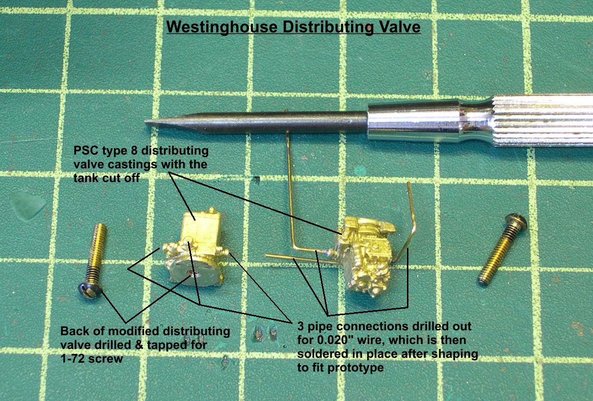
I also drilled holes for the 0.020″ piping and soldered pre-shaped wires into those holes before mounting the valves. Two of the pipes go back under the cab and disappear. The one coming out of the bottom of the valve and just jutting out to the left will be connected into a network of pipes a little later.
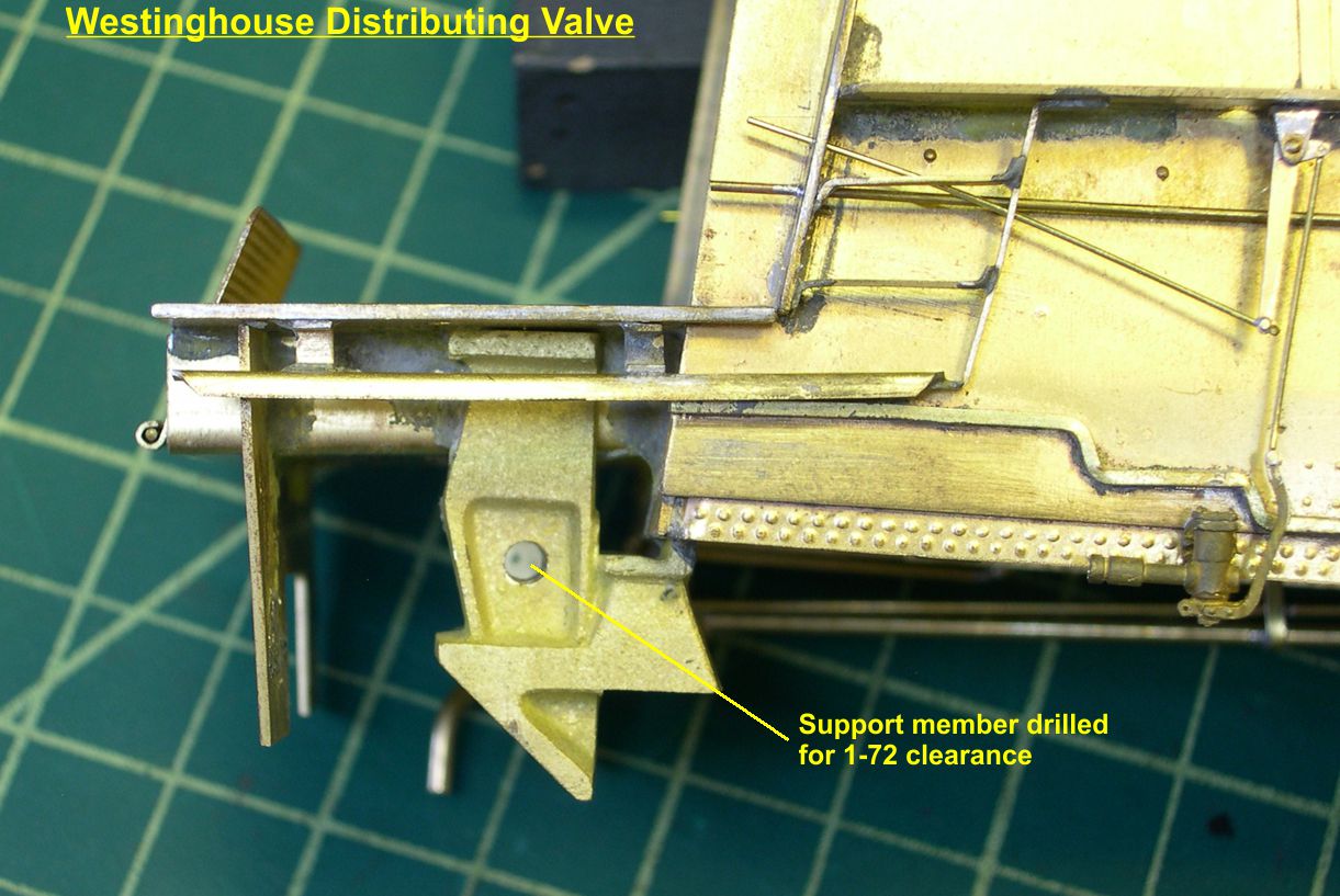
In photo “Distr Valve-2”, I show the 1-72 clearance hole drilled through the large support casting, so the distributing valve can be attached from the rear.
dist valve 2 ⤵
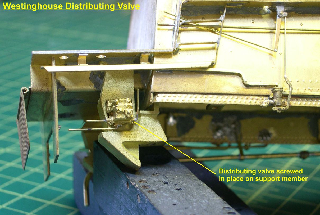
The next two photos, “Distr Valve-3 and 4”, shows the valve assembly attached from behind with a 1-72 screw.
dist valve 3 ⤵
dist valve 4 ⤵
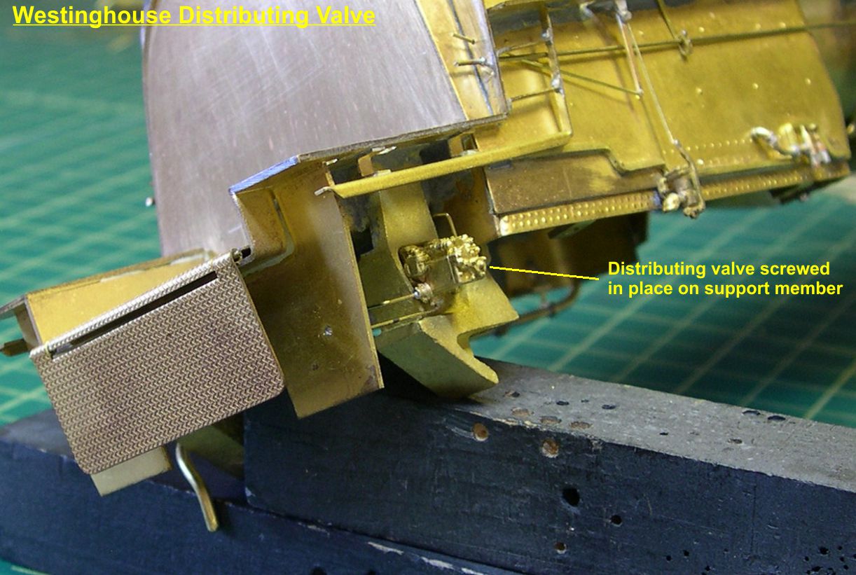
It looks for all the world like it is projecting through an opening in the support structure and it is exactly the right distance from the side of the engine. All in all, this worked out a lot better than I expected when I first saw the problem.
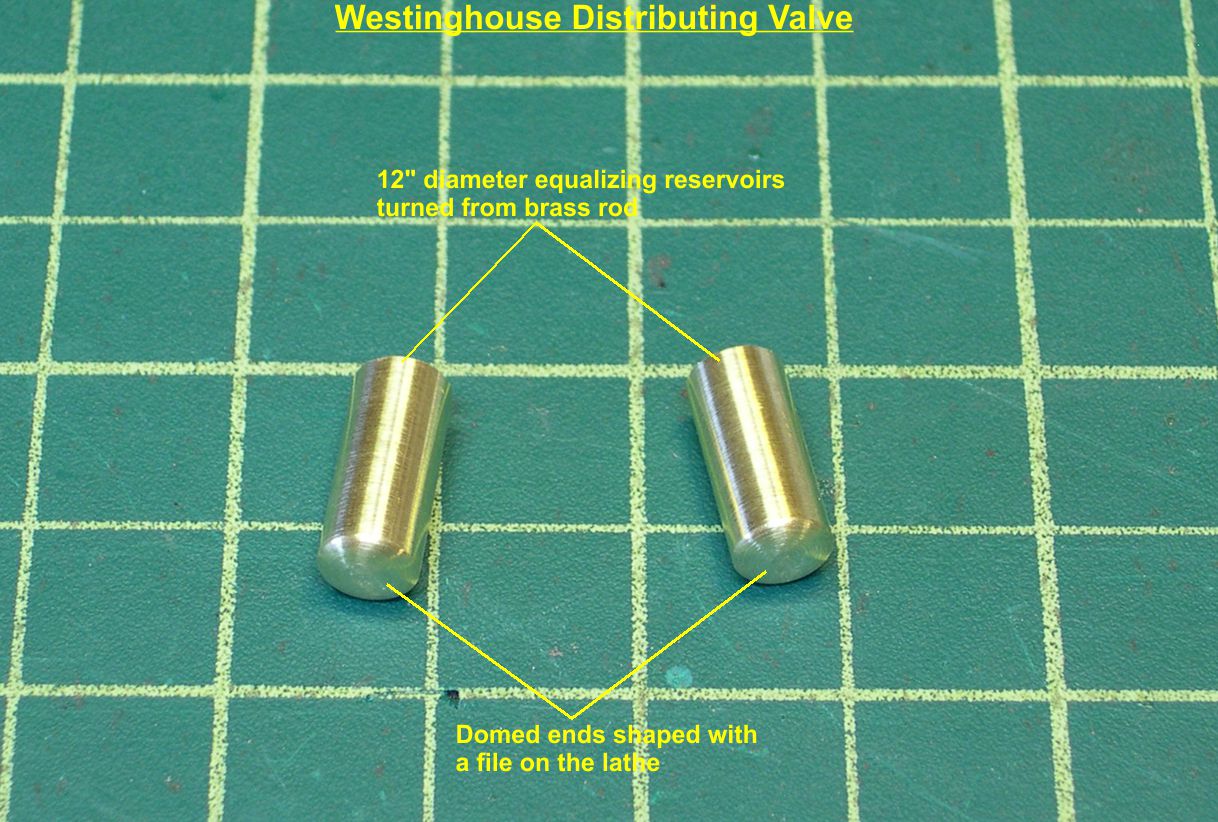
The equalizing reservoirs for the air brake system were 12″ diameter tanks. I turned these from brass rod. The domed ends were shaped with a file while spinning on the lathe. See photo “Distr Valve-5” to see the just turned tanks.
dist valve 5 ⤵
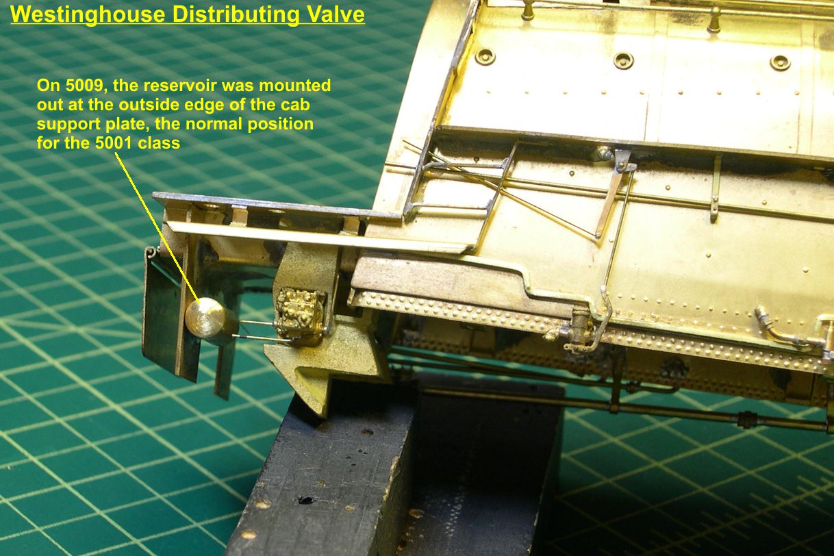
The reservoirs were mounted on the rear cab support plate. However, the two engines had the tanks mounted differently as shown in photos “Distr Valve-6 and 7”, which show the tanks soldered in place.
dist valve 6 ⤵

dist valve 7 ⤵
Next up is the injectors. These engines used a large Nathan non-lifting injector, for which PSC makes a nice casting. However, the casting has piping cast integral with the injector, which will not work well in this case. For one thing, the cast in piping is too small, so I cut it all off and drilled out the pipe connectors for the right size piping. See photo “Injector-1” for details.
injector 1 ⤵
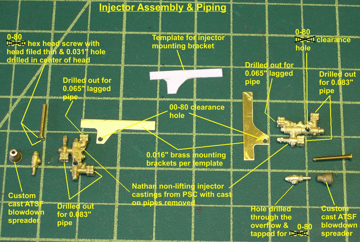
These injectors did not just hang on the ends of the steam and water pipes as you often see on models. They were securely mounted on a bracket attached to the frame end beam and cab support beam. Now I cannot duplicate that exactly, as I would no longer be able to take the frame and boiler apart if I did so. However, I was able to fake it pretty well. Using a nice close up photo of an actual 5001 class engine under the right side of the cab, I made up a template for the injector mounting bracket as shown in that first photo. I used that to make up two brackets from 0.016″ brass strip.
I wanted the rather complicated and intricate injector assembly to be nice and sturdy and not have the whole thing come apart every time I had to solder on another part. To accomplish that, I decided to hold all the main parts together with a screw. After tightening the screw with all parts in alignment, I soldered the assembly together. That pretty well makes it a solid piece for all practical purposes. The front of the injector has a hexagonal plate right in the center from which a pipe exits. That made the whole “screw it together” idea practical. I thinned the head on an 0-80 hex head screw to the right thickness, then drilled a 0.031″ hole in the center of the head down into the screw body for the pipe that will eventually exit there. I then drilled 0-80 clearance holes in the injector body and mounting bracket. The overflow, which is a separate casting, was drilled and tapped for an 0-80 thread. That done, I just slipped the screw through the injector and mounting bracket and screwed it into the overflow. Once everything was exactly aligned, I tightened the screw, rechecked the alignment, then soldered the whole thing solid. You can see how the front and back of the assemblies look right after soldering in photo “Injector-2”.
injector 2 ⤵
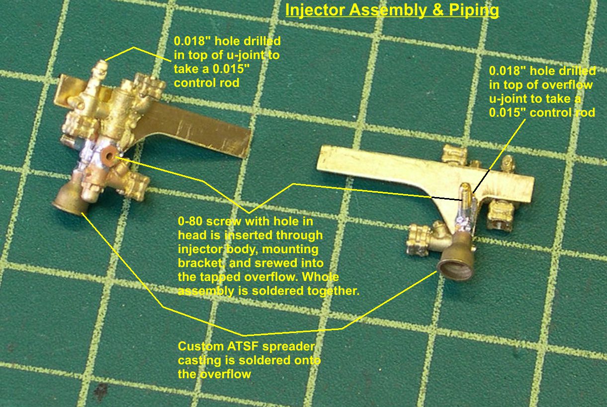
The ATSF spreader casting is one of the custom castings I had made for me from my masters by Dennis Mashburn a few years ago. I left the screw uncut for the time being, as it is a nice handle.
There is still a lot of detailing to do at this point. I soldered a piece of 0.031″ wire into the hole in the center of the hex screw head and soldered a pipe elbow to it. I’ll add the pipe later so it does not get knocked off with handling (at least not so often). I then soldered 0.083″ brass rod into the pipe openings for the cold water pipe and the pipe to the tender. On the tender pipe, I added a piece of 0.040″ wire to hold the tubing that will serve as the hose to the tender. The cold water pipe was shaped to put the injector at the right location once it was connected to the rest of the cold water pipe. The cleanout casting from PSC serves as the connection point to the main water pipe as well as detailing. There was a bracket holding the cold water pipe to the injector mounting bracket, so I modeled that with strip brass and simulated bolts from Scale Hardware. At the other end of the mounting bracket were two bolts that held the bracket to the rear cab support beam. I used slightly larger simulated bolt heads from scale hardware for these. The right, or forward end of the mounting bracket was bent 90 degrees and welded to the end beam. I bent and cut the bracket to shape, so it will rest on the end beam, simulating the connection there. It is also necessary to drill 0.018″ holes into the tops of the u-joint castings on the water inlet and overflow to accept 0.015″ control rods from the cab later on. See photo “Injector-3” to see how the assemblies look at this point just prior to final mounting.
injector 3 ⤵
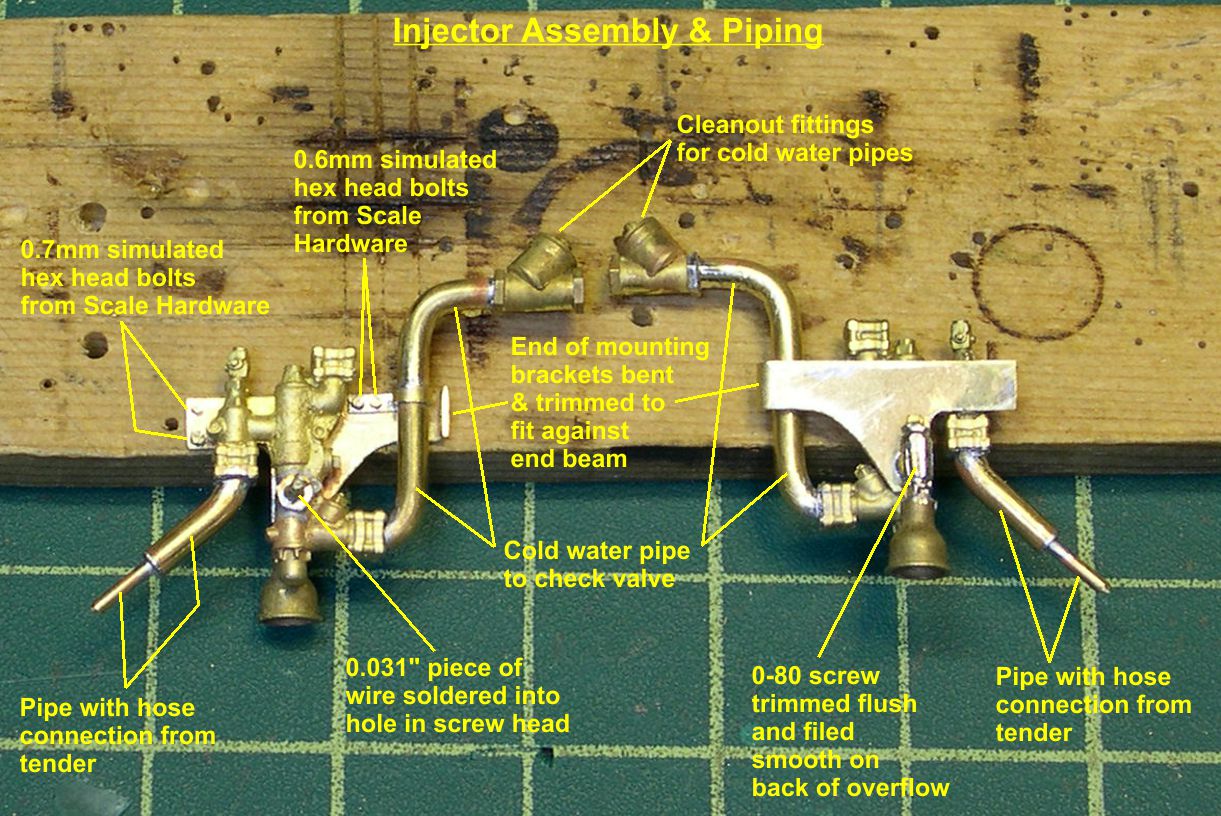
In that photo, I have finally cut off the protruding end of the screw and filed it flush with the overflow.
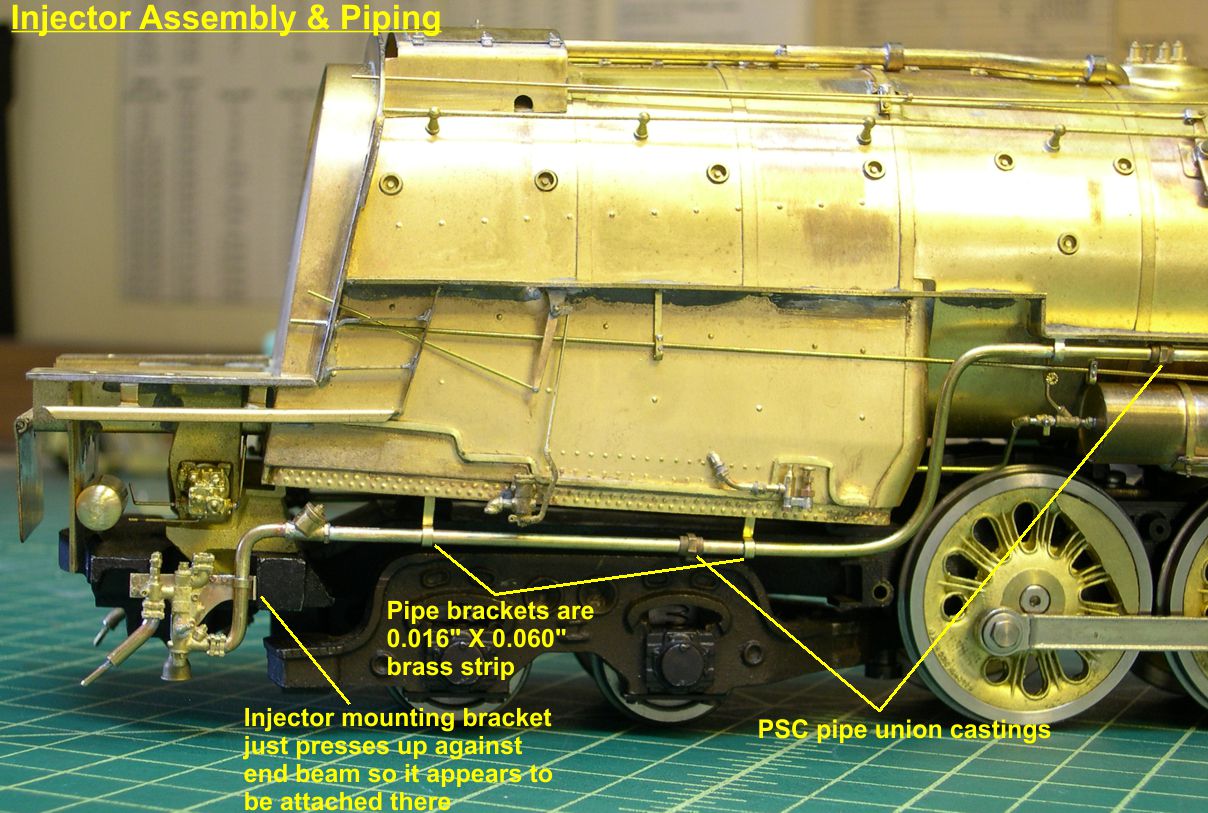
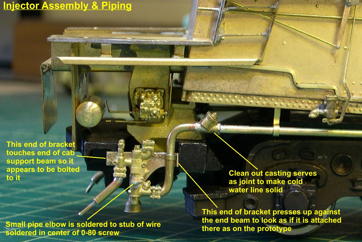
Final mounting of the injector assembly was accomplished by bending the cold water pipe to shape, then soldering it in place with a couple of pipe unions for detailing and the necessary pipe brackets to hold it. Then I soldered the injector assembly to the cold water pipe using the cleanout castings as the joint for strength. You can see in photos “Injector-4 and 5” how the injector mounting bracket fits up against the end beam to simulate the connection there.
injector 4 ⤵
injector 5 ⤵
The whole thing is pretty sturdy already, but adding the lagged steam supply pipe from the turret to the top of the injector will stiffen it even more. That will happen in the next episode. Photo “Injector-6” shows the rest of the cold water pipe installed along the right side of the engine.
injector 6 ⤵
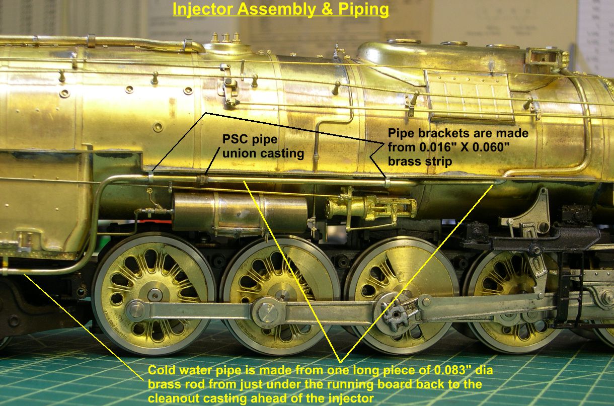
The part of the pipe above the running board that goes up to the check valves was installed much earlier and terminated at the running board. I just shaped the end of the pipe below the running board so it appears to pass through the running board instead of being two separate pieces.
I am still not done under the right side of the cab, of course. Next, I will do the lagged steam supply pipe from the turret, a pipe matrix that connects to the “dangling” pipe from the distributing valve, the control rods for the injector from the cab, and the pipe from the middle of the injector. Until then, enjoy model RRing.