AT&SF Class 5001 Finished Tender Trucks
I have now finished all the brass work on these two big engines. The attached 15 files show the final detailing of the tenders and how the entire engine-tender combo looks.
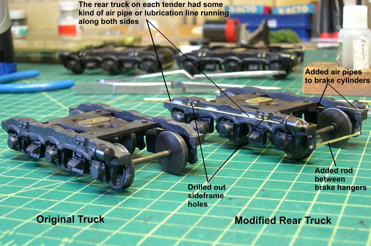
I started the detailing of the frame with the trucks. The USH trucks are well done but a bit sparse on details. I drilled out the holes that they had left as dimples. Then I added the rods that go between the brake hangers, although I only did this on the ends where they can be seen. I also added the air pipes to the brake cylinders. The rear trucks each had a pipe running along the side of the truck frame. I don’t know whether this was an air line or lubrication line, but only the rear truck had it. It was difficult to fit up, as it has to lay flush to the sideframe across the humps in the sideframe. Earlier, I had replaced the USH wheelsets with much nicer NWSL 145 profile wheelsets. Photos 15 and 16 show the comparisons between the as built and modified trucks.
tender 15 ⤵
tender 16 ⤵

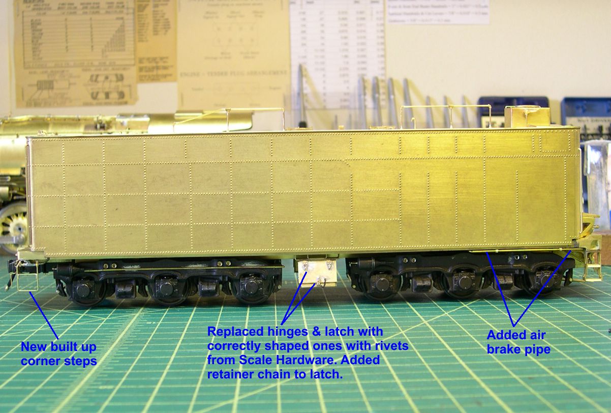
Photos 17 and 18 show modifications to the right side of the tender.
tender 17 ⤵
tender 18 ⤵

The air brake pipe on the prototype was visible under the right front side until it dived in under the frame. That was missing on the USH model. The rear steps were not very accurate, so I built up new ones constructed exactly like the prototype. Likewise, the hinges and latch on the tool box between the trucks were pretty crude, so I replaced them with exact size, detailed parts. I used Scale Hardware rivets for the rivets on the hinges and latch. The retaining chain was so the pin holding the latch closed would not get lost when removed. That is actual chain on the model.
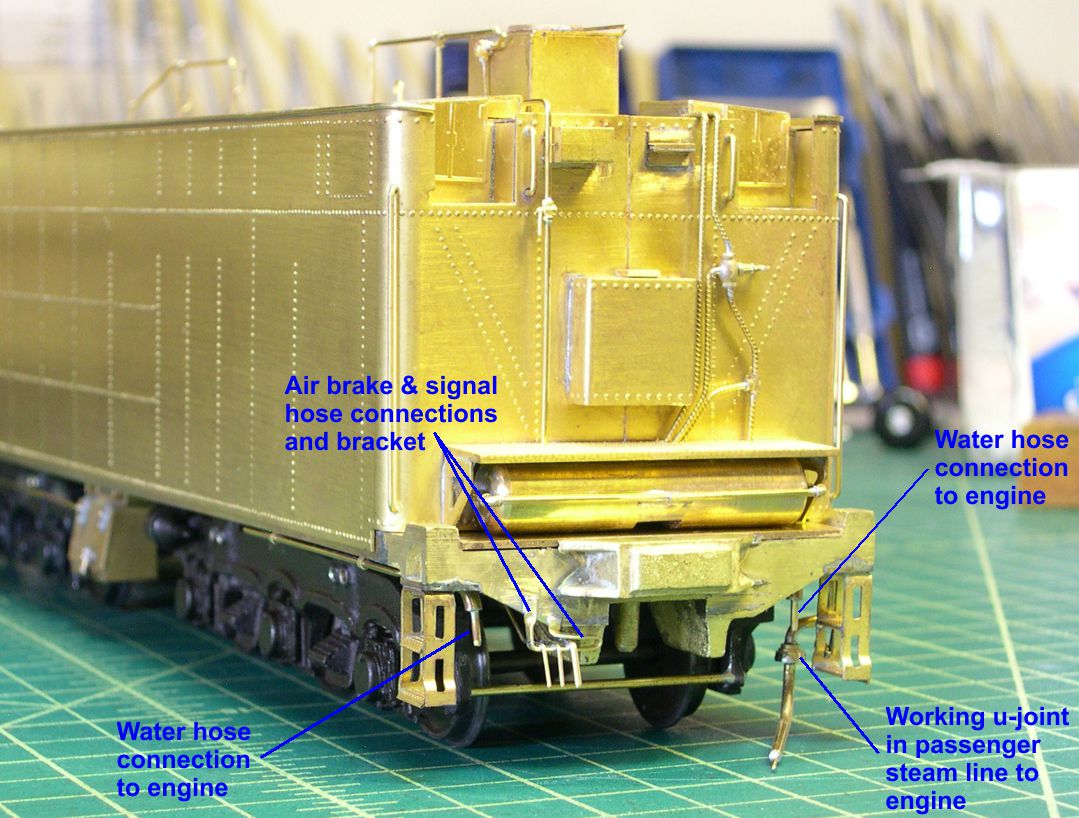
Major work was required on the rear endsill. As produced, the model had a passenger buffer. While the 5001 class engines did have a passenger tender, it did not have the buffer installed. I had to saw off the buffer and mill out the channel that a buffer would have filled to get the right appearance. Then I rebuilt everything on the rear endsill. As mentioned, the rear steps were built up just like the prototype. So were the cut lever brackets, again using Scale Hardware rivets. The cut lever was bent exactly like the prototype and installed in the brackets, and I used PSC gladhand and angle cock castings for the air hose. I could never find any definitive photo of the rear of one of these tenders, so I do not know if they had the passenger steam fitting and signal hose installed or not. I have seen examples of passenger capable tenders on other engines which did not have those fittings installed. I assumed that they would not have had anything other than an air brake hose, since they never got the passenger buffer. Now you can bring out your photos proving me wrong and make me correct that assumption. Photos 19 and 24 show the rear end mods.
tender 19 ⤵

tender 24 ⤵
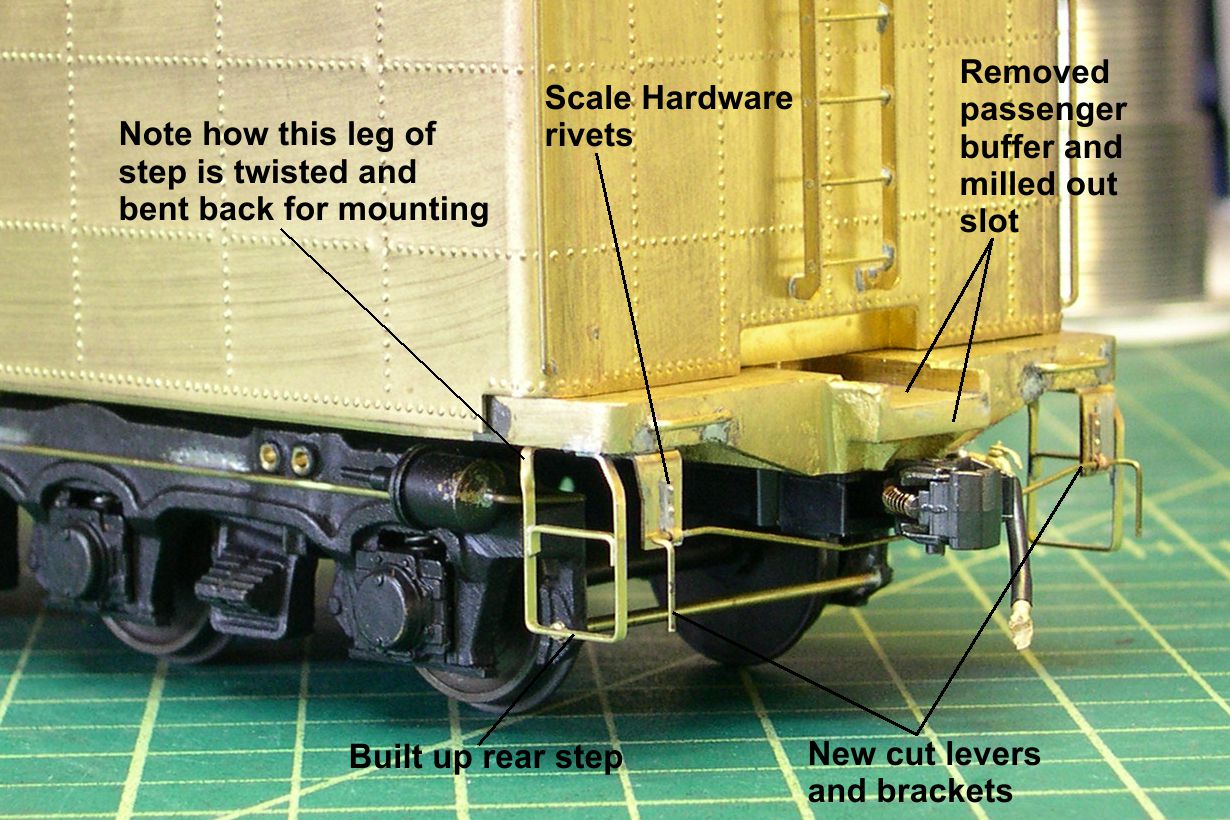
Photo 20 shows the left side mods.
tender 20 ⤵
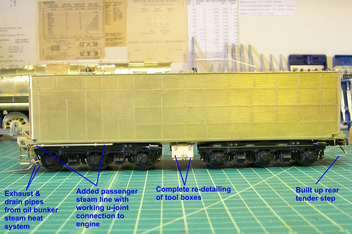
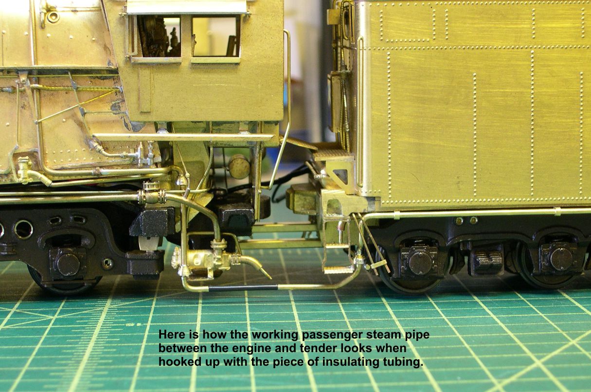
The same tool box and rear step changes were made. The passenger steam pipe with its working u-joint to the engine had to be installed under the left front of the side. The u-joint is made exactly the same as on the engine. Photo 23 shows the engine and tender hooked together with the insulated tubing connecting the ends of the working passenger steam line.
tender 23 ⤵
Also on the left side, just behind the front steps, were two small pipes. These were the drain and exhaust pipes for the steam heater system in the oil bunker. Many photos show small wisps of steam coming from these pipes.
Photos 21, 22, and 26 show the changes made to the front of the frame.
tender 21 ⤵

tender 22 ⤵
tender 26 ⤵
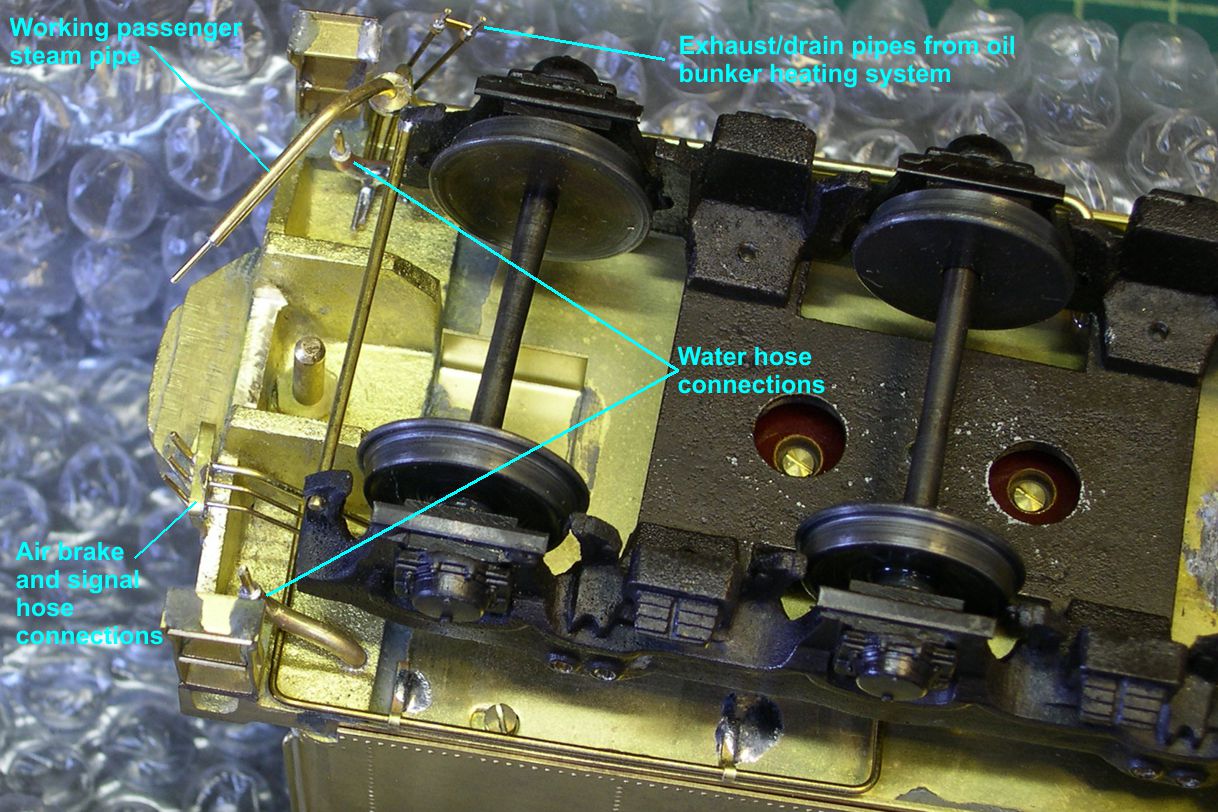
The large water pipes on each side were installed with fittings to allow hoses to slip on them. I had to bend up that strange looking bracket for the air brake and signal line connections. I don’t know why such a funny shape was used, but someone thought it was a good idea.
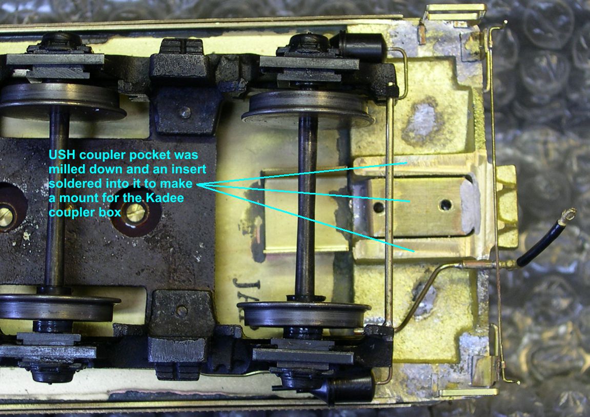
Finally, while milling the top side of the rear endsill, I also milled the bottom side to the right height for the Kadee coupler box. I had to fit an insert into the opening in the endsill casting and solder it in place. Then I drilled and tapped 2mm holes for mounting the coupler box as seen in photo 25.
tender 25 ⤵
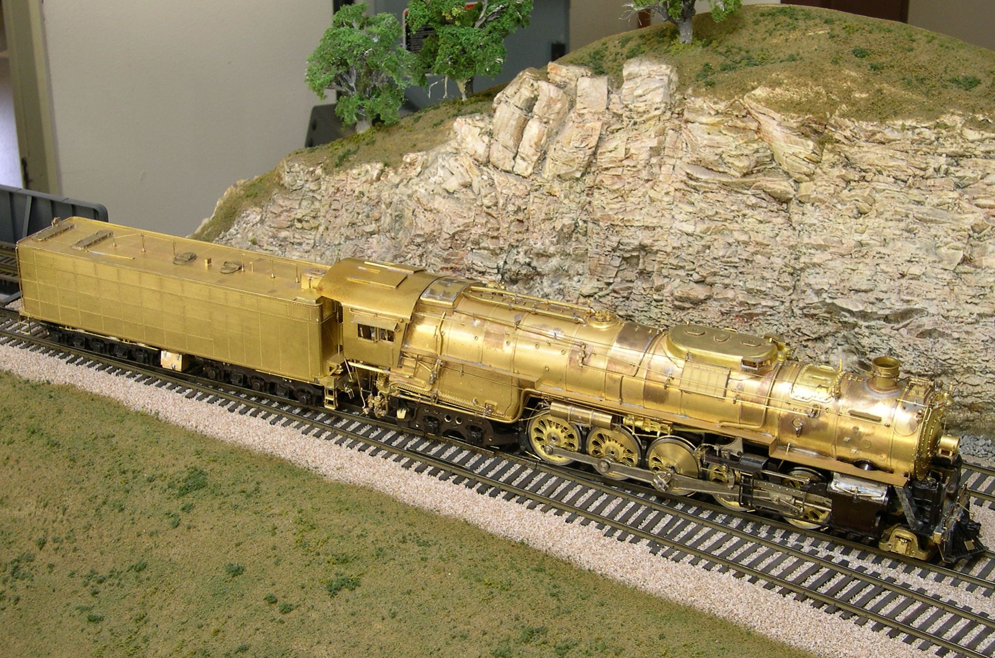
Photos “Finished-1,2,3” show what the totally modified engine and tender look like coupled together.
finished 1 ⤵
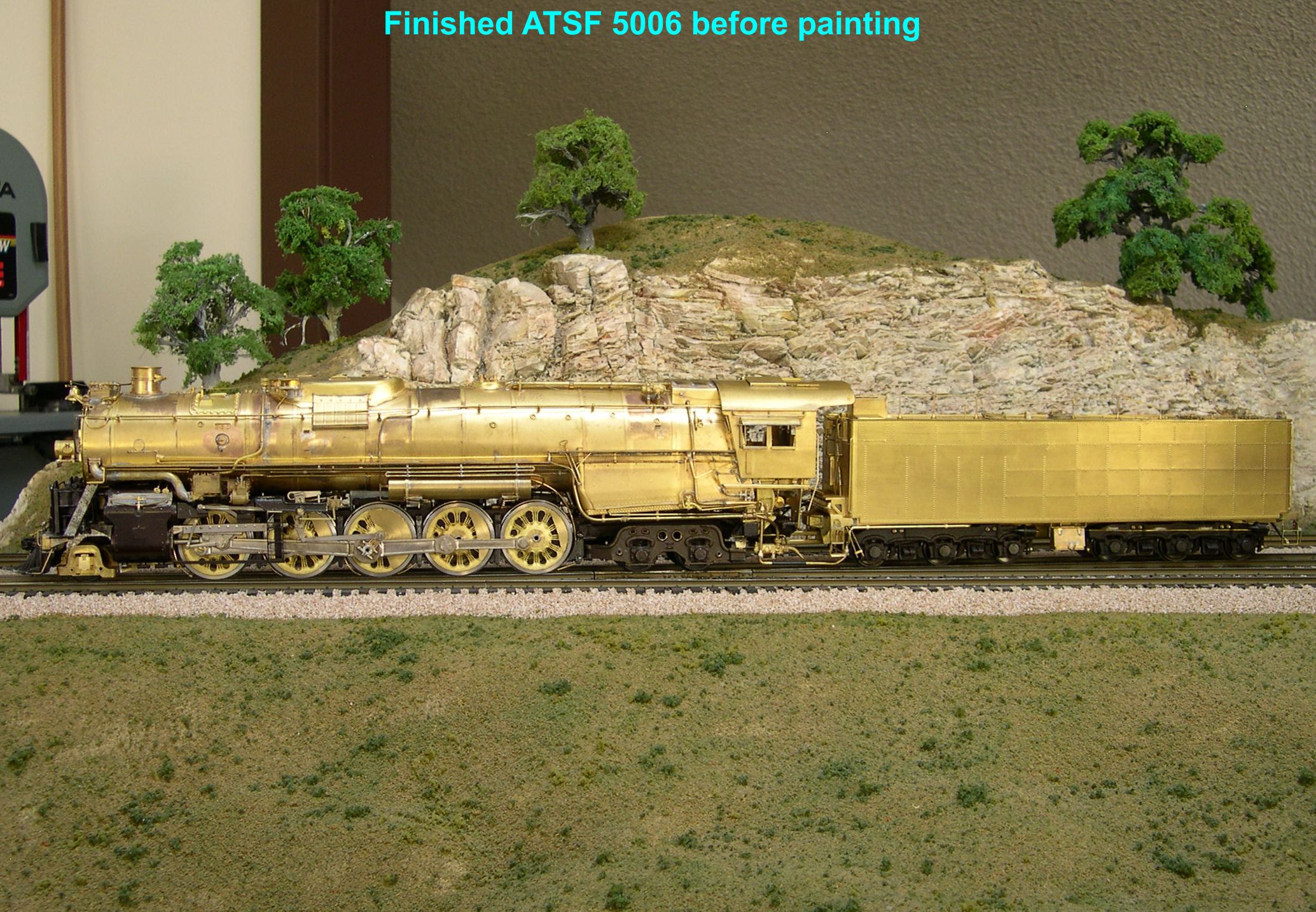
finished 2 ⤵
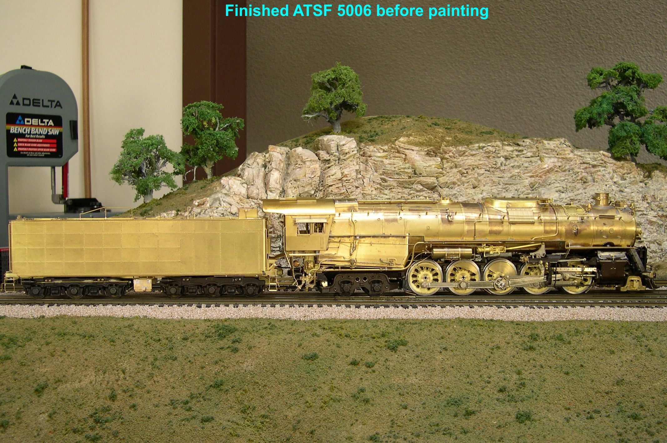
finished 3 ⤵
Now it is time to start into the painting process. I’ll go into a little more detail on how I paint an engine than usual starting in the next installment.