AT&SF Class 5001 Dry Pipe Brackets – Power Reverse – Generator
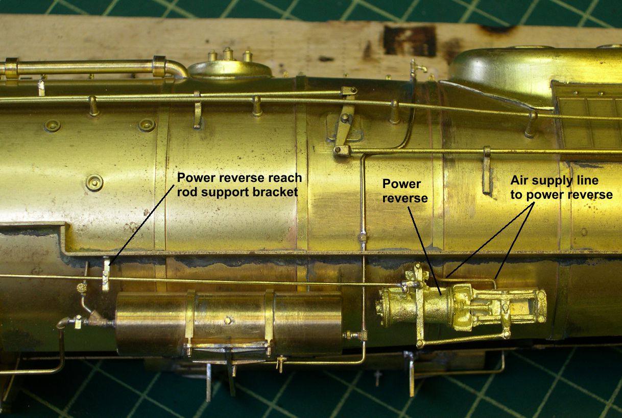
In this episode, I continue installing appliances and plumbing. There are 14 photos attached showing how I did certain things. Let’s take a look at the power reverse first. No one makes the exactly correct Baldwin power reverse casting. However, the Baldwin must have been a close copy of the Alco since there are only very minor differences. PSC makes the Alco casting, and I have some of them. However, as I compared the PSC casting and the original USH casting, I discovered that the USH casting is actually slightly better, so I re-installed it instead of replacing it. Before I did so however, I drilled holes in it for the reach rod and the air pipe and installed the air pipe. The air supply pipe on these big Texas types actually went slightly forward from where it enters the power reverse, then turns back toward the boiler and disappears under the lagging. I have extensive video of ATSF 5030 on display at Santa Fe, NM, and the lagging is missing on it, so I could easily trace what happens to the pipe. It goes back to the turret ahead of the cab dodging in between stay bolts all the way. In photos “Power Reverse-2 and 3”, you can see the air supply line pointed out.
power reverse 2 ⤵
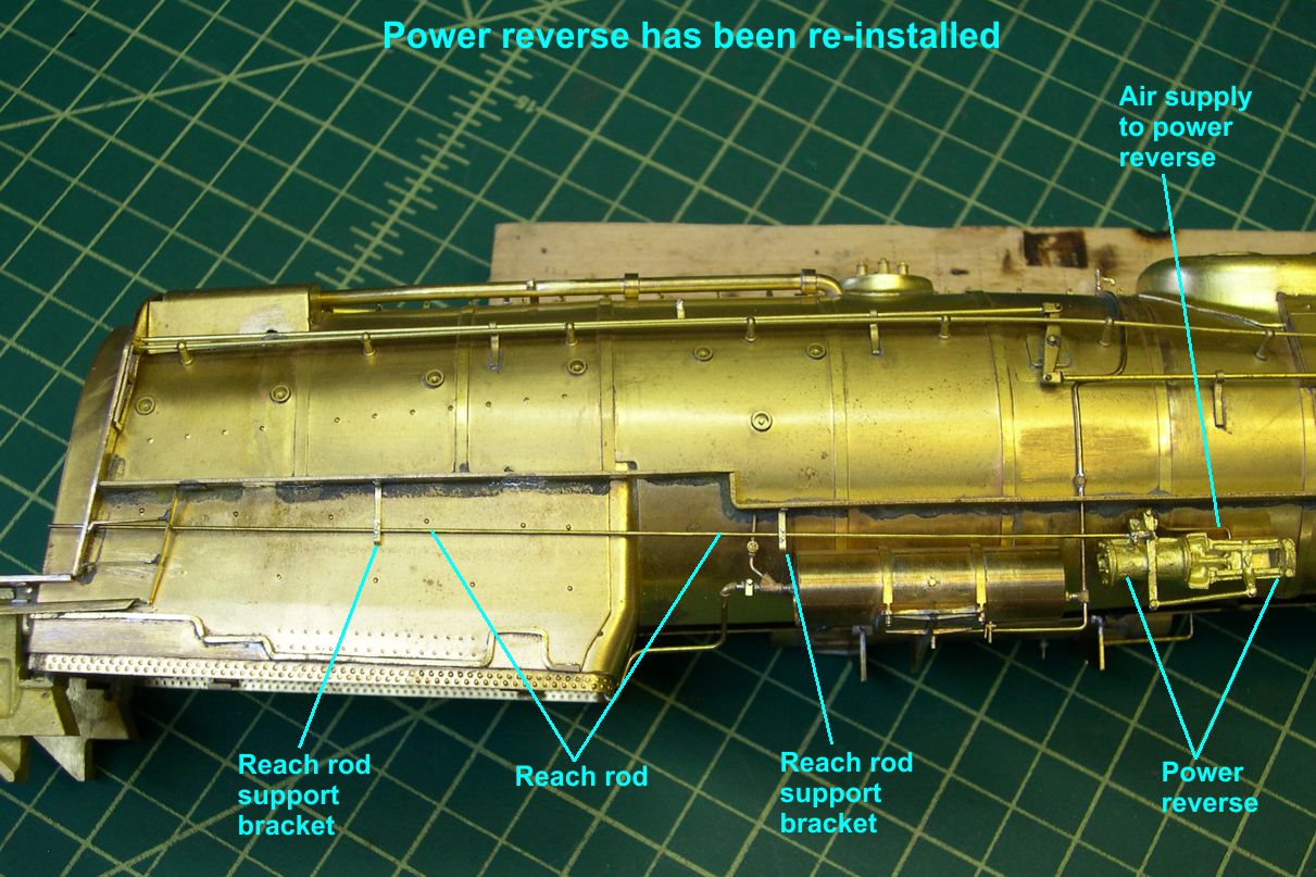
power reverse 3 ⤵
The reach rod for the power reverse is straight forward, just a straight piece of brass wire from the cab to the power reverse. However, that rod is supported by some fairly complex brackets that I had to fabricate. In photo “Power Reverse-1”, I have shown the parts necessary to build the brackets.
power reverse 1 ⤵
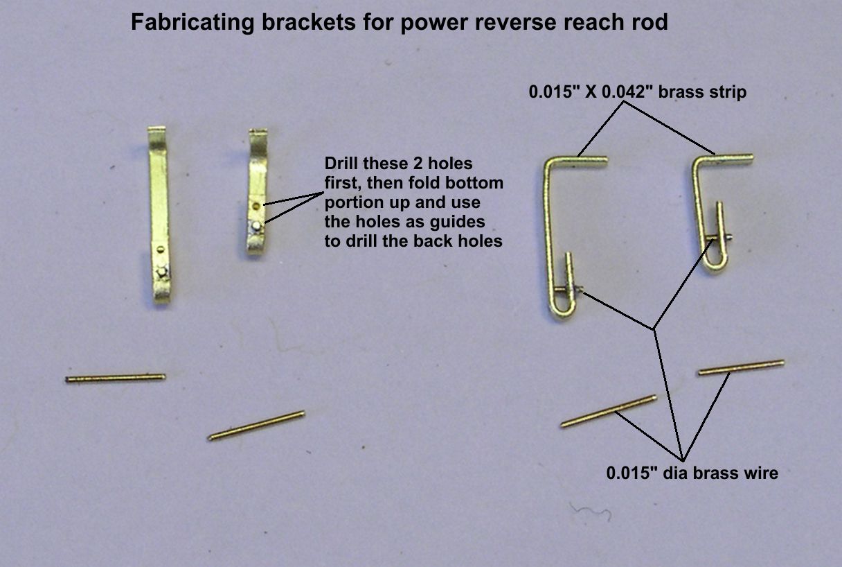
There are two brackets for each engine, one long and one short. I installed the reach rods first so I could measure exactly how long each bracket needed to be. That does make the installation of the brackets a bit more difficult, but either way it can be a little tricky. Step one is to drill the two 0.016″ holes in one end of the brass strip. Then you bend the strip up into a “U” shape as shown. The “L” bend at the top is positioned so that the reach rod will just pass over the bottom pin in the bracket, which will go into the bottom hole. Now use the existing holes to guide the drill bit in drilling on through the back side of the bracket. This way, the holes line up perfectly. Solder the bottom pin into the bottom hole, trim the back off and file it smooth, then trim the front of the pin to project out slightly as shown in the photo and file the top of it flat. Do not install the top pin yet. Now the brackets are ready to be installed.
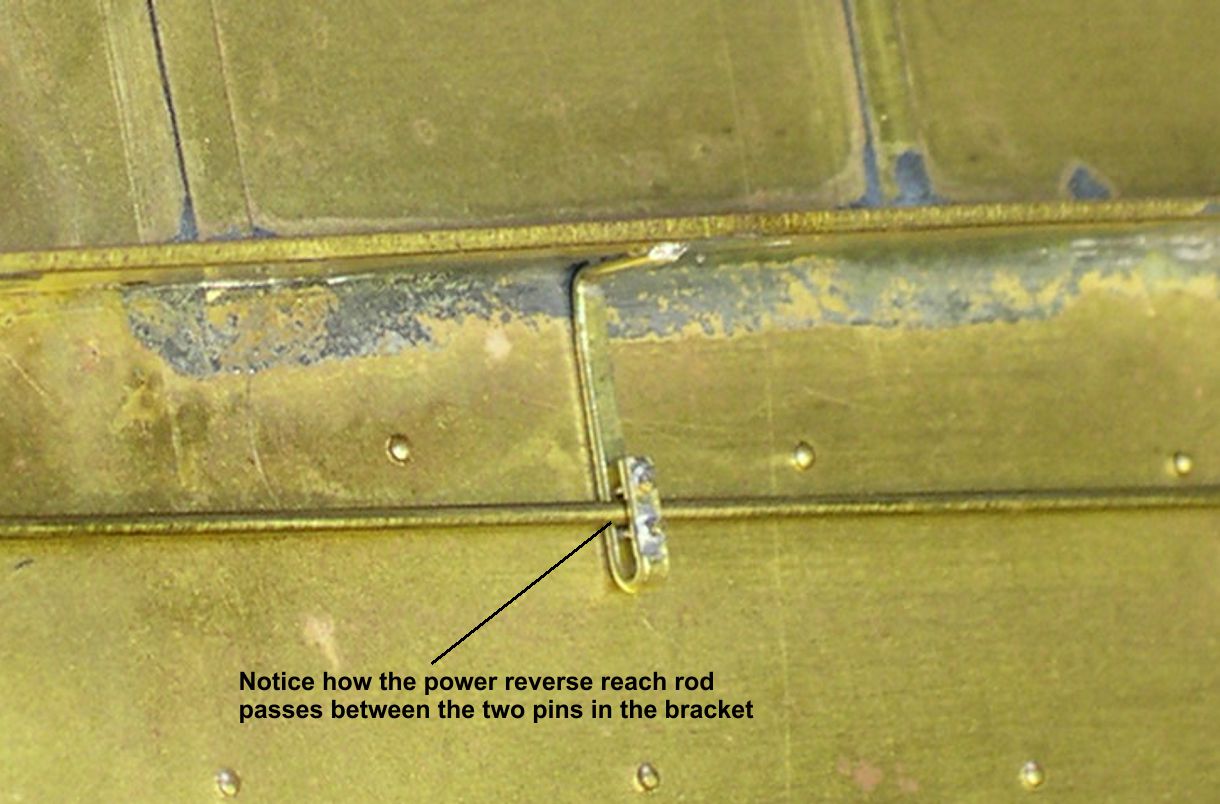
Photo “Power Reverse-2” shows where the brackets are installed. I just slipped the brackets over the reach rod, inserted and soldered the top pins in place, trimmed the top pins to match the bottom ones, and then soldered the brackets in place. On the prototype, I suspect that the pins, at least the bottom one, may have held a roller to make the rod move more easily, but that is not very practical in O Scale. Anyway, as you can see in the photo “Power Reverse-4”, the brackets are interesting looking additions without being too hard to make.
power reverse 4 ⤵
The generator casting on the original USH engine was totally wrong. PSC makes the correct Sunbeam casting, so that is what I used. Before mounting the generator, it is a good idea to drill holes for the various connections to it. The junction box on the side just has very shallow holes where the cables connect, so I drilled those out much deeper. The hole for the steam supply pipe for the turbo needs to be drilled out, too. I also did the turbo exhaust mods described below before starting to mount the generators.
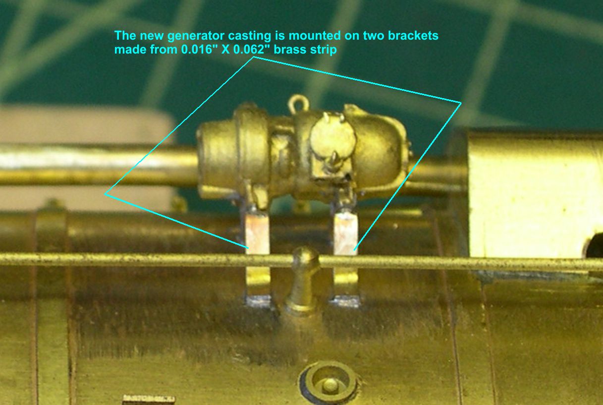
Photo “Generator-1” shows how the new generator casting is mounted on two brass strips rather than a platform as you see so often on models.
generator 1 ⤵
There was actually a slight difference between 5006 and 5009 on the turbo exhaust from the generator. 5006 used a simple, conventional pipe elbow to direct the exhaust toward the center of the boiler. The elbow on the casting faced the wrong way, so I had to cut it off and replace it with a PSC elbow. I drilled out the opening on that elbow, so the exhaust opening will appear to be open on the model. The 5009 had a more elaborate exhaust pipe arrangement. I also had to cut off and replace the pipe elbow on this one, but I added a hollow tube with a pipe union in the middle of it. It looks as if ATSF was trying an experiment on 5009, perhaps to help keep the turbo exhaust steam out of the fireman’s eyes better. First, they added the shorter section of pipe, then they added another section using the pipe union. The experiment must not have been worth it, as 5009 appears to be the only engine to get this special exhaust. Photos “Generator-2, 3, and 4” show the different installations of the exhaust.
generator 2 ⤵

generator 3 ⤵
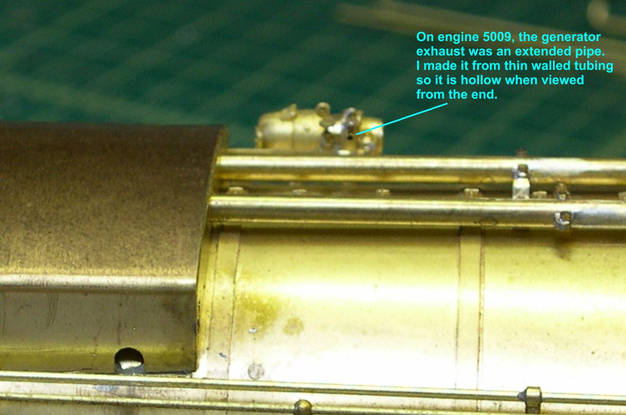
generator 4 ⤵
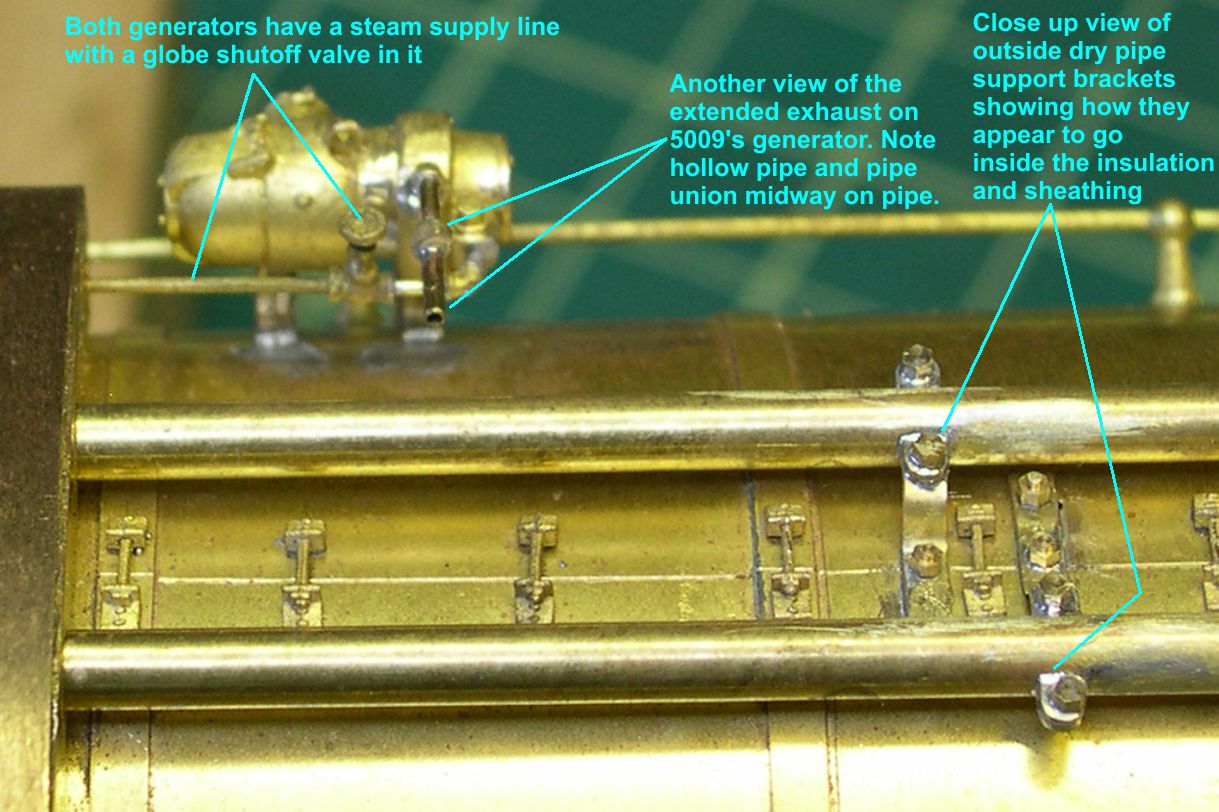
The steam supply line casting with globe valve was supplied with the generator. I had to extend the forward end of it slightly on 5009 to let the globe valve clear that long exhaust pipe.
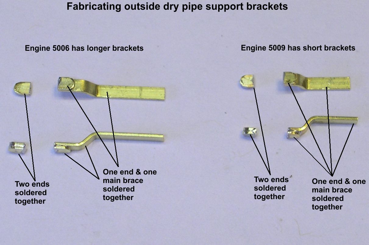
The final item on this segment is the brackets that support the outside dry pipes on top the boiler. What makes them complicated is that the insulation and steel sheeting over the dry pipes hid the center portion of the brackets. Only the two ends with large hex bolts showed on each side of the dry pipes. (No wonder USH made no effort to model these.) You can see in photo “Generator-4” how I was able to simulate the brackets passing through the insulation and sheathing. Starting with photo “Dry Pipe Brackets-1”, I am going to show you how I did the simulation of those brackets.
dry pipe brackets 1 ⤵
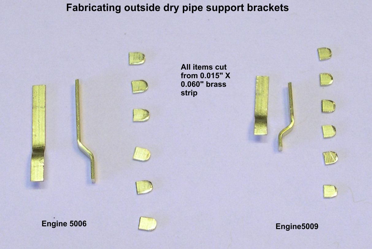
Photo “Dry Pipe Brackets-1” shows the various parts required for the two engines. Remember that the dry pipes are farther apart on 5006, so the brackets for 5006 are longer than for 5009. In photo “Dry Pipe Brackets-2”, I have soldered together pairs of little tabs and little tabs to main brackets to represent the visible portions of the brackets.
dry pipe brackets 2 ⤵
In photo “Dry Pipe Brackets-3”, I have drilled holes through each pair and soldered in 1.0mm simulated hex head bolts from Scale Hardware.
dry pipe brackets 3 ⤵

Photo “Dry Pipe Brackets-4” shows the parts ready for installation after the bolts were trimmed and the bases of the brackets were curved to match the top of the boiler.
dry pipe brackets 4 ⤵

At this point, I soldered the small, outside ends in place on the dry pipes and then located the positions of the large mounting bolts on the top of the boiler and drilled holes for them in the brackets. I then used the holes in the brackets as guides to drill holes in the top of the boiler. I used simulated 1.0mm hex nuts on studs from Scale Hardware for the mounts to the boiler top. I tack soldered the main brackets in place, then inserted the simulated nuts on studs and soldered them from underneath. I also soldered the ends of the main brackets to the dry pipes to seal any seams, as none were visible on the prototype. Photos “Dry Pipe Brackets-5 and 6” show the completed brackets on the two engines.
dry pipe brackets 5 ⤵
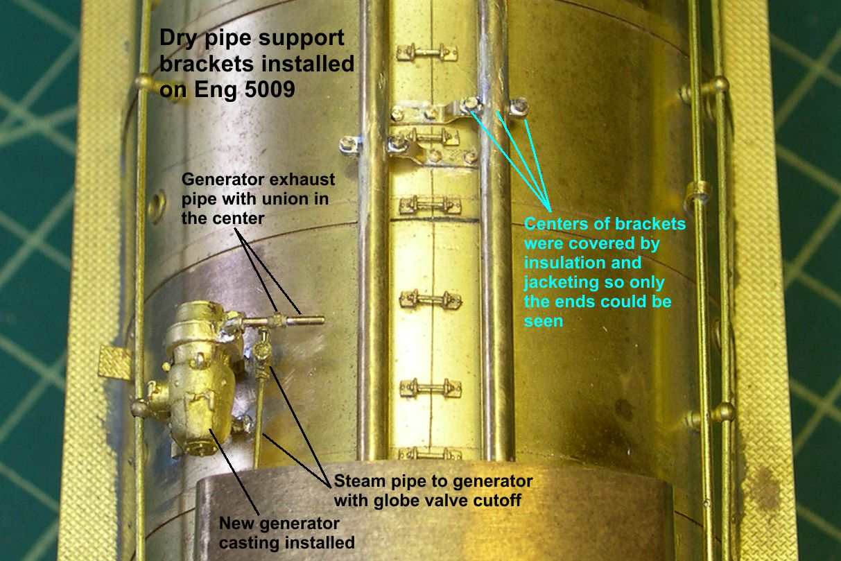
dry pipes brackets 6 ⤵
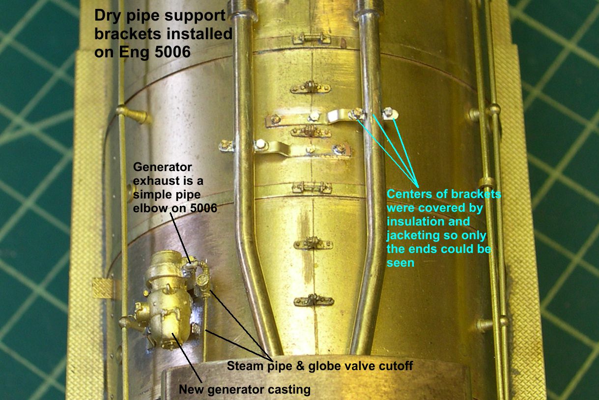
You can also see some additional generator details in those photos.