AT&SF Class 5001 Air Tanks
At the end of the last segment, I went off to research whether or not ATSF engines did, indeed, have a vertically rolled up canvas curtain over the rear cab opening. I had questioned this due to something I read in the ATSF Society’s painting and detailing guide for steam engines. Upon re-reading, I realized that what they were saying was that such curtains were not standard until after 1938, when they were added to all new engines. Not all older engines got them, just the ones serving in colder areas. Bottom line is: These 5001 class engines, as well as all the big modern engines had the curtains. Hence, I have added the circular brackets to hold the curtains as seen in photo Cab-16.
cab-16 ⤵
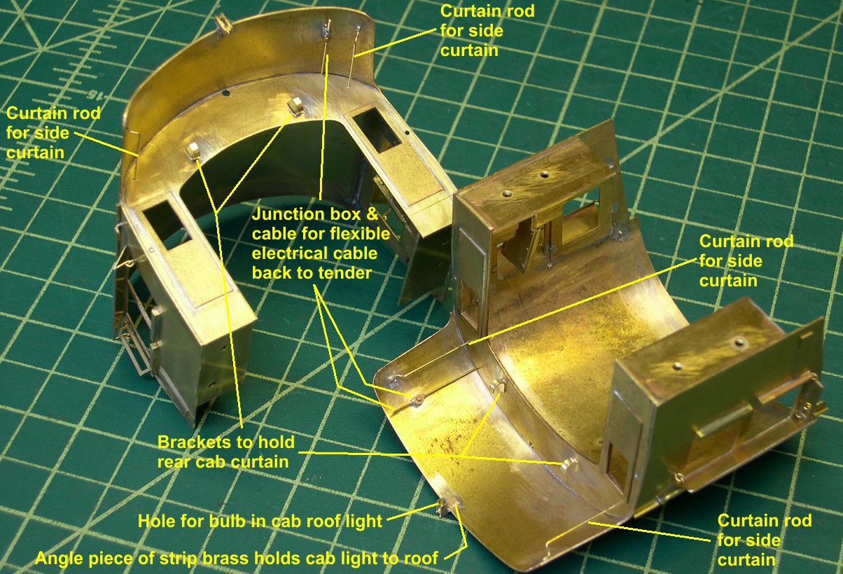
I also remembered to add the electrical cable and junction box for the flexible electrical cable that goes back to the tender. That pretty well finishes the cab exterior.
Next, I tackled the new air tanks. The 5011 class engines had domed ends on their air tanks, and USH modeled them correctly. What they did not do correctly was the mounting of the tanks. On the USH models, the tanks are mounted directly on the boiler, and the tanks are even tapered on the backsides to make them fit there. They should stand out from the boiler coming out even with the outer edges of the running boards. On the 5001 class, the air tanks had flat, recessed ends. Curiously, the air pipe connections on these flat ends were not all centered. The rear connections were centered, but for some unknown reason, the front connections were offset slightly from the center. On the left, or fireman’s side, the connection was offset to the inside, toward the boiler. On the right, or engineer’s side, The offset was toward the bottom. I have no clue why they did that.
Starting with photo Air Tanks-1, I have attached 18 photos showing the construction and mounting of the new air tanks. Some interesting problems are addressed. The tanks were 22.5″ in diameter. That is 0.47″ in O Scale, so one has to start with 1/2″ diameter brass rod. You can cut that size rod with a hacksaw or even a jewelers saw, but a band saw is much faster. A band saw can whack through large brass sections very quickly, so I get a lot use out of mine as shown in photos 1 and 2.
photo 1 ⤵

photo 2 ⤵

The length of the two tanks are 6.5′ and 11.5′ prototype. That translates to 1.625″ and 2.875″ in O Scale. Be sure to add about 1/2′ to each piece, so you have something to mount in the lathe chuck.
In photo 3, a piece of brass rod has been chucked up on the lathe and a preliminary cut across the face, or “facing” cut has been made.
photo 3 ⤵
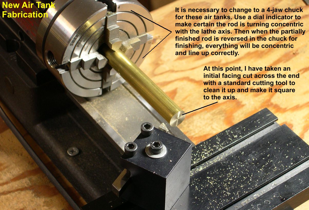
It is important to use a 4-jaw chuck for these operations on the air tanks, because you will have to turn the tank around and do more machining on the other end. Any slight “runout” or non-concentric positioning of the rod in the chuck will result in bad results upon flipping the piece end for end later. Use a dial indicator to make certain there is no wobble to the rod as it rotates. With a 4-jaw chuck, you can independently move each of the 4 jaws until the part is exactly concentric with the chuck meaning there is no wobble during roatation. In the same photo 3, you can see the standard cutting tool set up to turn down the diameter of the rod to 0.47″. In photo 4, you can see that the whole length of the tank has been turned down to 0.47″, and I am using a boring tool to do the indented tank end.
photo 4 ⤵
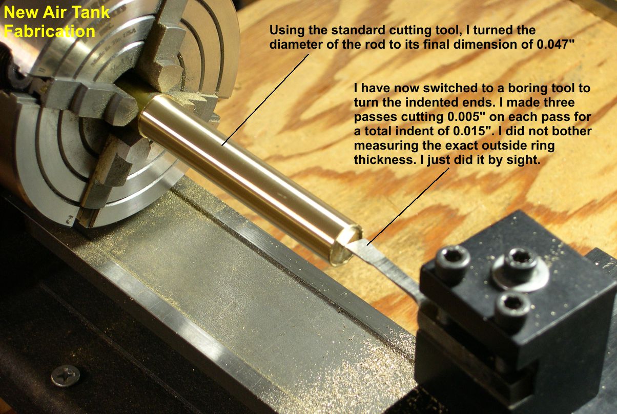
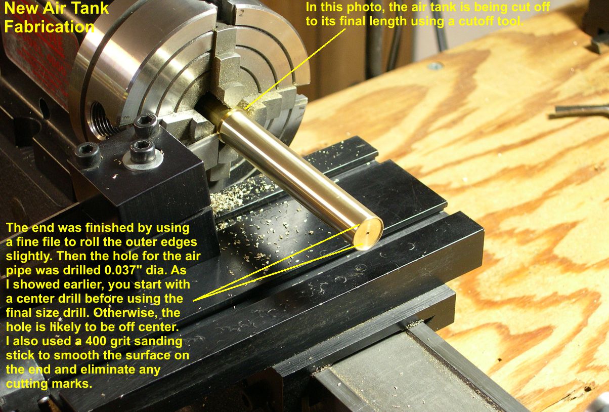
Ordinarily, you would drill a starting hole for the boring tool, but I want a very flat, but fairly shallow end. You can feed the boring tool in about 0.005″ per pass without needing a starting hole, and you do not risk a dimple in the center of the end by over shooting with the drill. I did not bother with exactly measuring the rim I was leaving. I just did it by sight, roughly 20-30 mils thick. After 3 passes with the boring tool resulting in a 0.015″ indent, I used a fine file to round the outer edge of the rim slightly and then used a 400 grit sanding stick to smooth the flat end and remove tooling marks. This will be the end with a centered air pipe, so I drilled a 0.037″ diameter hole for the pipe before changing the setup. In photo 5, you can see the tank being cut off to its exact length using a cutoff tool.
photo 5 ⤵
In photo 6, I have removed the cut off stub of 1/2″ rod and flipped the air tank end for end to mount it back in the chuck.
photo 6 ⤵
This is where the 4-jaw chuck really pays for itself. By centering up the tank in the chuck using a dial indicator as shown, you can machine the second end without any misalignment. Getting the piece centered up so the dial pointer does not move more than one small division during an entire rotation is sufficient. With even more effort, you can make the pointer just sit there rock steady while the piece rotates, but that’s kind of overkill for this operation. It’s good for drivers and other really precision jobs though. This job is strictly visual, and you can’t see 0.001″ of non-concentricity in the finished end, so I see no reason to go the extra mile. I’m just anal, not totally insane. The second end is done exactly the same way as the first one using a boring tool.
photo 7 ⤵
However, this end will have the offset pipe connection, so I did not drill a hole this time. I drilled the offset holes using my milling machine as a drill press. In photo 8, you can see a close up of the two different ends.
photo 8 ⤵

It is much easier to install the pipe connections into the tanks now than it will be later when they are mounted onto the boiler. I have been collecting up small sections of air pipe with a union on them that I cut off of something before use. Unfortunately, I do not remember what casting they come off of, but they are ideal for this application. (Always knew they had to be good for something.) They do not need to be very long, because there are pipe fittings right near the tank on the various air pipes. You can do the exact same thing with 0.036″ wire and some union castings. I just got lucky when these salvaged pieces fit perfectly. In photos 9 and 10, you can see the stubbed off pipe fittings soldered into the ends of the new tanks.
photo 9 ⤵
photo 10 ⤵
Now comes the really challenging part of this segment: How do you solder those slippery round tanks to a bracket and then to the boiler so they are positioned exactly right? Just holding the tanks is a challenge, as the very smooth surfaces make them like trying to hold jello. After doing some measuring on the erecting drawing and thinking it over, I came up with a plan that worked pretty well. First of all, the tops of the tanks were exactly 12″ below the bottoms of the running boards – a really nice figure, 1/4″ for O Scale. So to begin with, I clamped a piece of 1/4″ X 1/4″ brass bar stock to the bottom of the running board. That provides a nice sturdy vertical reference I can press against with no fear of moving it during soldering. A little more thought lead to placing shims under the ends of the tank to position it horizontally. By using the correct thickness shims, one can position the tank until the outside edge is exactly in line with the outer edge of the running board, as it should be. See photos 11 and 12 for these positioning steps.
photo 11 ⤵
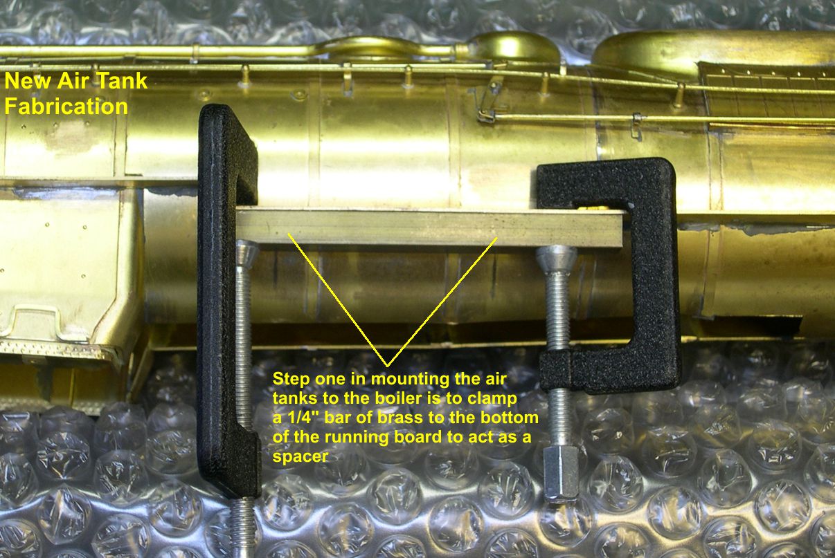
photo 12 ⤵
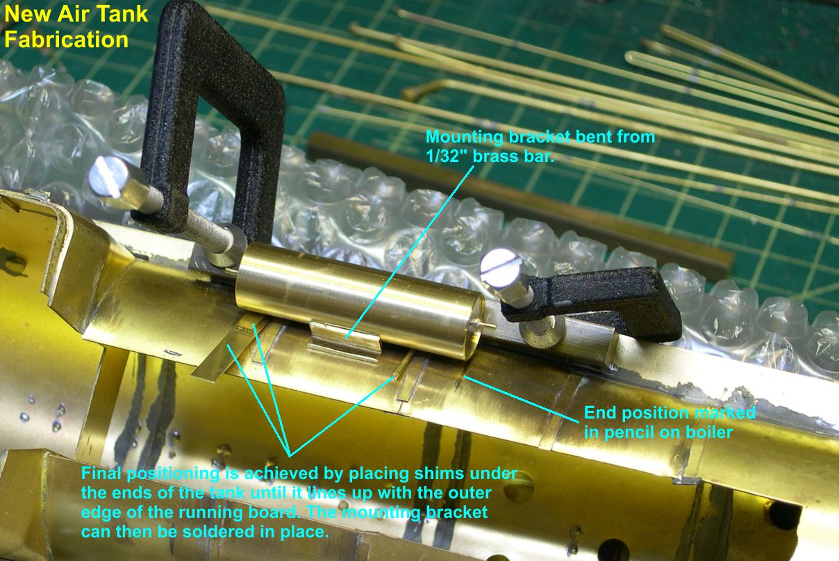
I used brackets crudely bent from 0.032″ brass bar stock for mounting brackets as seen in photo 12. The real thing had fancy brackets cast integral with the frame for mounting the air tanks. I will have to build up reasonable facsimiles of those brackets, but using them for the actual mounting is out of the question. Appearance of the 0.032″ brackets is not important, as they will be pretty much hidden by the built up ones. Before doing the actual soldering to the bracket, I had to make sure the offset air pipe stub was properly positioned, as there would be no changing it afterwards. Photo 13 shows how the soldered bracket and air tank look right after soldering.
photo 13 ⤵
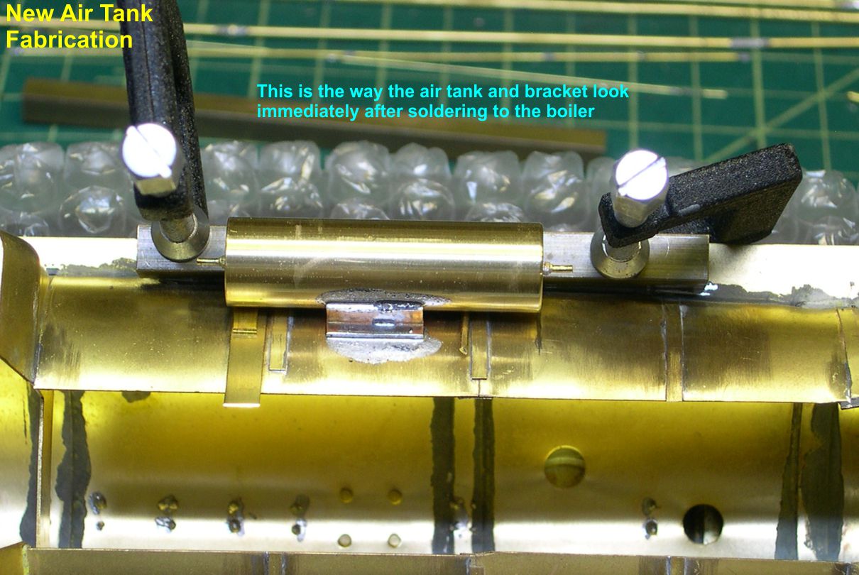
I have mentioned a number of times how I use a dull but smooth Exacto blade and sanding sticks to clean up solder joints. I figured it was time to show you what those look like and what the surfaces look like after each operation. Photo 13 shows the surfaces right after soldering. Photo 14 shows how they look after I used the Exacto blade to cut and scrape the excess solder away.
photo 14 ⤵

That is a number 16 Exacto blade, by the way. It gets into a lot of places a number 11 won’t and is a lot stronger than a number 11. Get some, you’ll like them. Photo 15 shows the finished surfaces after sanding with a 400 grit NWSL sanding stick shown in the photo.
photo 15 ⤵
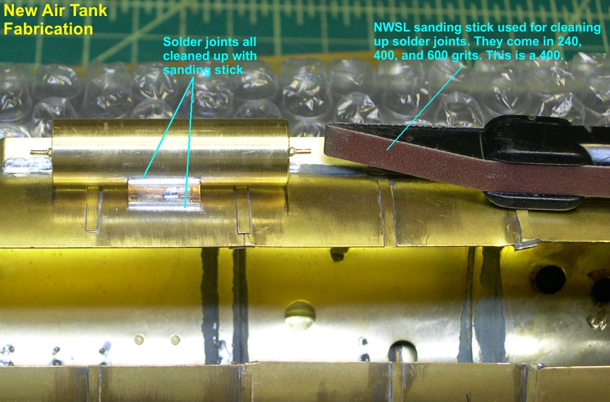
Don’t know how I would live without these sanding sticks. A 240 grit is great for removing traces of solder and sanding out cuts and deep scratches in brass. 400 generally gives a good smooth surface for painting and 600 almost polishes the surface when smoothness is really critical.
The low angle front side view in photo 16 shows how invisible the mounting bracket is at normal viewing angles.
photo 16 ⤵
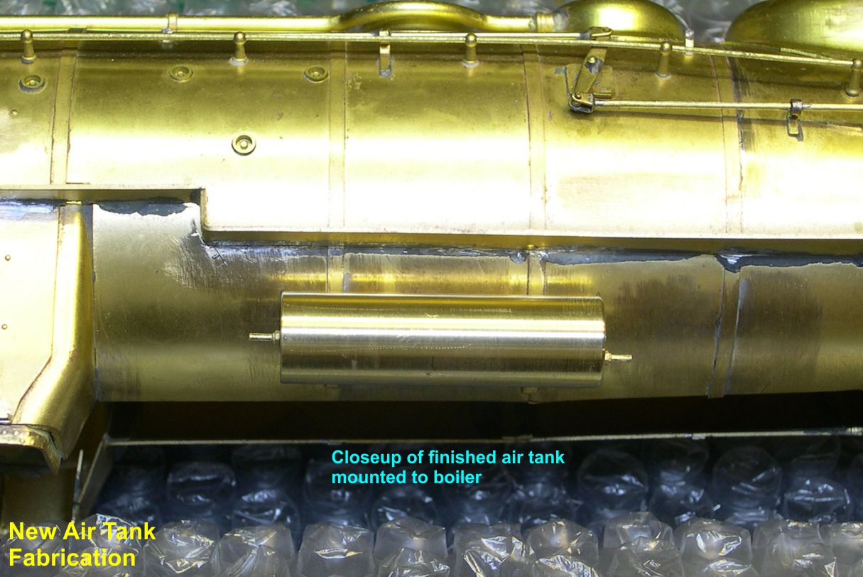
Photos 17 and 18 show the new air tanks mounted on the engine.
photo 17 ⤵
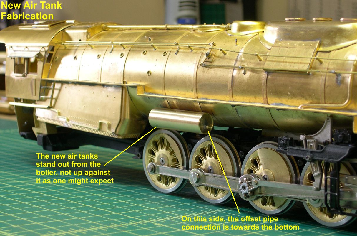
photo 18 ⤵
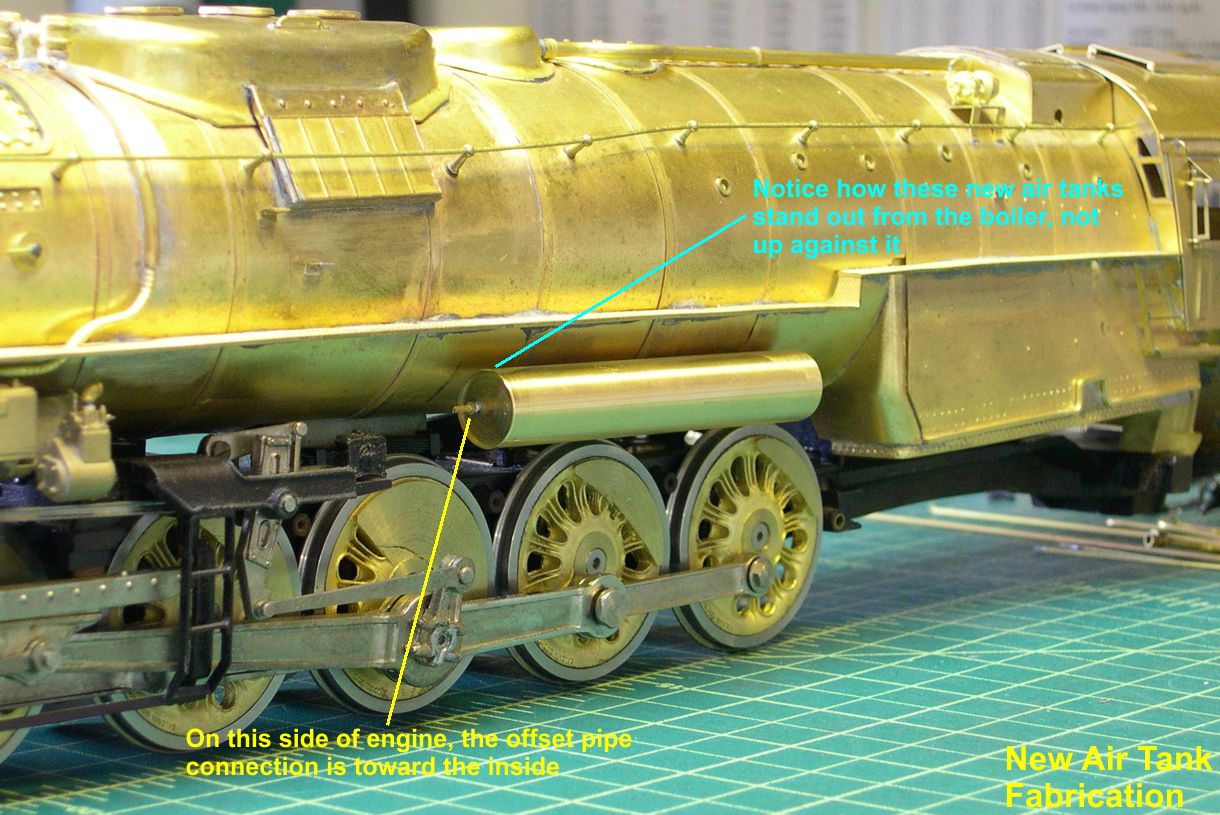
They make the model appear a trifle fatter, as they are not tucked back under the running boards as on the original USH model. They come right out to the edge of the running boards and do not actually touch the boiler, as on the prototype. Now I have to figure out how to build up the faux brackets for these tanks, along with the bands that hold them in place.