AT&SF Class 5001 Stack – FWH – Gladhand
Part 8 of this 2-10-4 saga is going to consist of two parts. First, I finished up the plumbing around the Worthington SA feedwater heater and added lagging clamps to the top of the boiler. Secondly, a number of interesting questions and comments have come up about the way I am doing the model and about the prototype. I will digress briefly from describing work on the model to answer some of these questions and give some more info about the prototype itself.
There are 7 photos attached showing the latest additions to the models. Photos 17 through 20 are 4 different views of the finished plumbing around the feedwater heater.
photo 17 ⤵
You may remember that the air exhaust pipe from the FWH was installed as just a stubbed off wire after removing the original pipe that had the pipe elbow installed facing the wrong direction for this model.
photo 18 ⤵
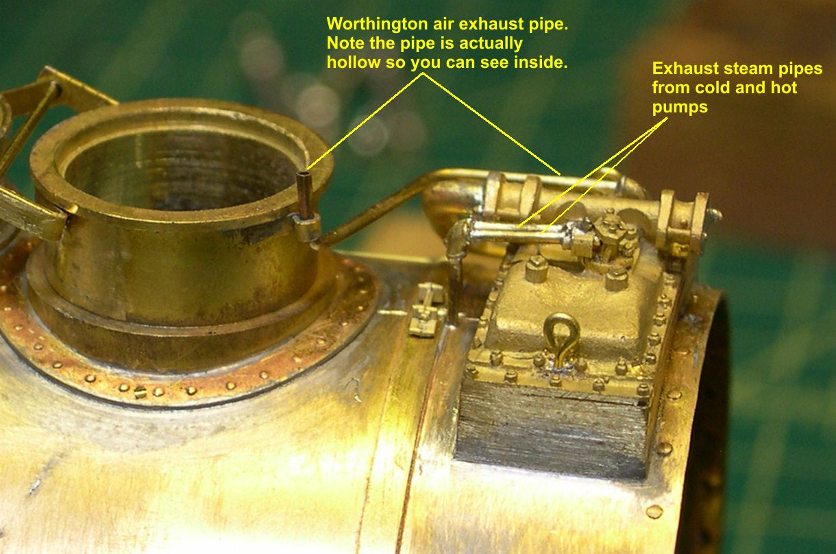
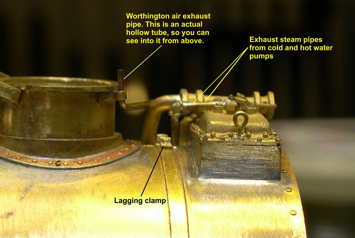
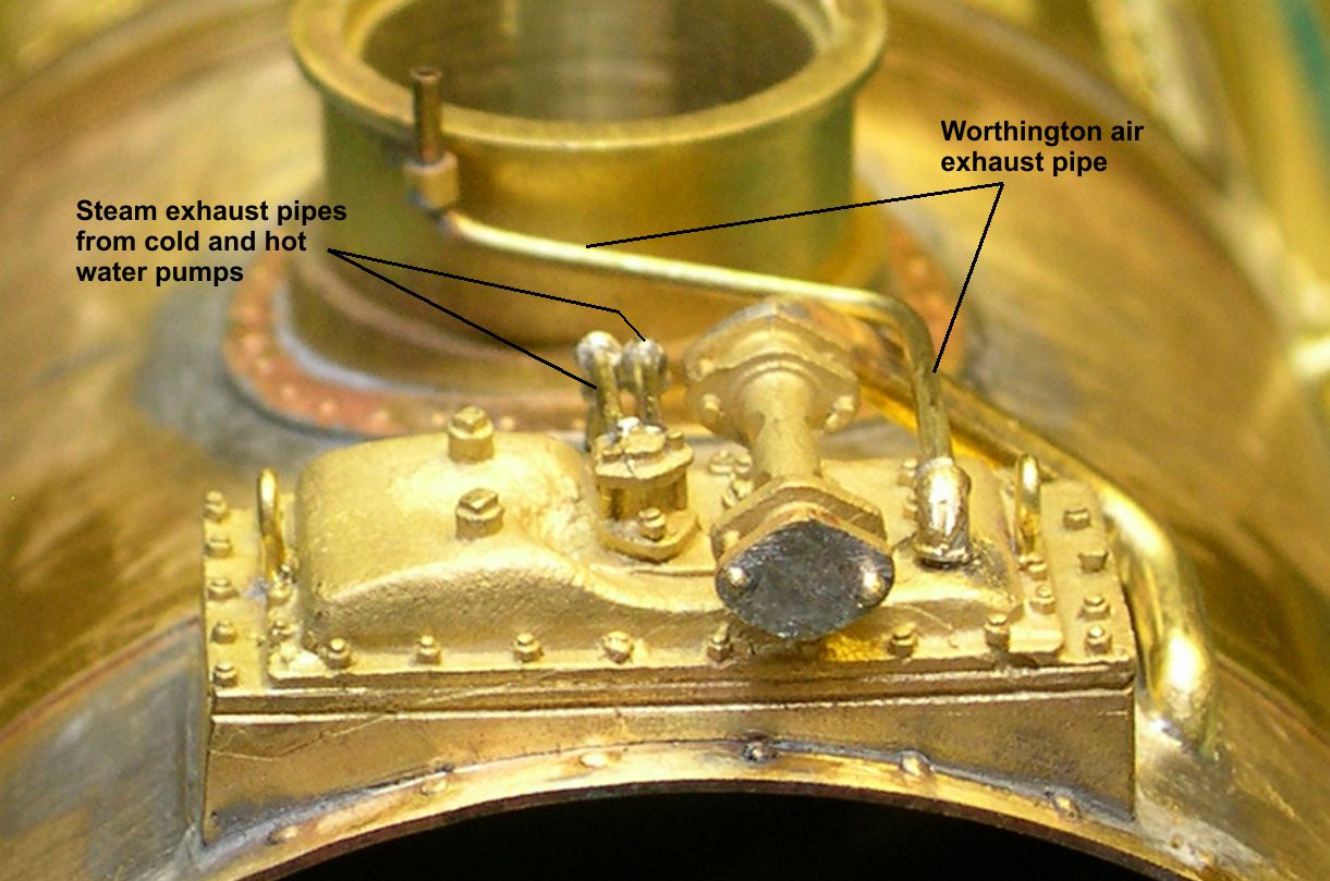
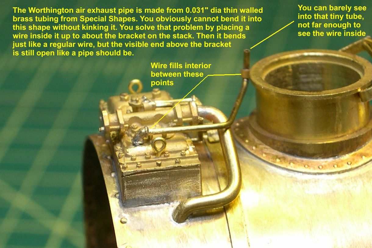
I have now installed a new pipe elbow on that exhaust pipe and run the completed pipe over to a bracket on the stack. I used 0.031″ diameter thin walled tubing from Special Shapes for this pipe, so you can actually see an opening at the top of the pipe as there should be.
photo 19 ⤵
Now you cannot bend tiny tubing like this easily without kinking it. My solution was to put a brass wire inside it, one that barely fits. The wire only goes up to about the bracket on the stack, so it does not ruin the illusion of a hollow pipe, but below that, it allowed me to bend the tubing just like solid wire. That’s a really tiny tube, so you can’t see far enough into it to see the blockage farther down. Hollow tubes like this for open pipes are a nice touch on a model. I did the same for the open air pump exhausts on my SP AC-12 Cabforward.
photo 20 ⤵
Two smaller pipes exit the top of the FWH heading rearward, turn downward using pipe elbows, and disappear under the jacketing. These are the steam exhaust pipes from the Worthington cold water and hot water pumps. That exhaust steam gets recycled in the FWH providing some more free heating of the feed water for the boiler.
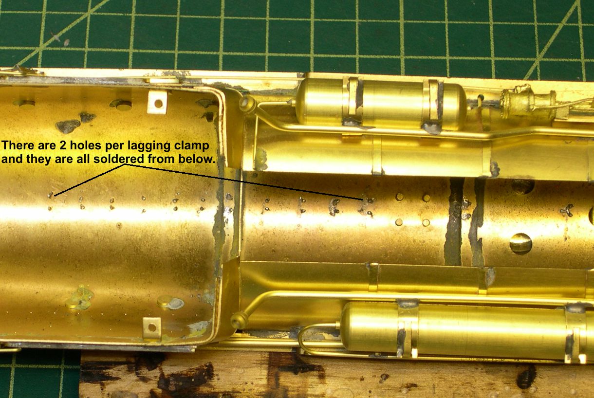
At this point, I decided it would be a good idea to get all the boiler lagging clamps installed before I install too much other delicate detailing to get in the way and potentially damaged. There is a lot of drilling involved in installing all those clamps, as each clamp casting has two legs to insert in holes. First though, I used a very sharp steel scribe to scribe parting lines along the top of the boiler for the sheets of steel that cover the asbestos lagging. The lagging clamps hold those sheets together along the top of the boiler. Note that all the boiler bands need lagging clamps to hold them together also. Modelers and importers alike often forget the boiler band clamps when installing lagging clamps. After scribing the parting lines, I located and drilled all the holes for the clamps. I then soldered all of them in place from underneath, so no solder cleanup is needed. See photos 21-23 for views of the lagging clamps and their installation.
photo 21 ⤵
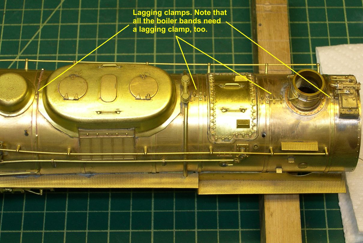
photo 22 ⤵
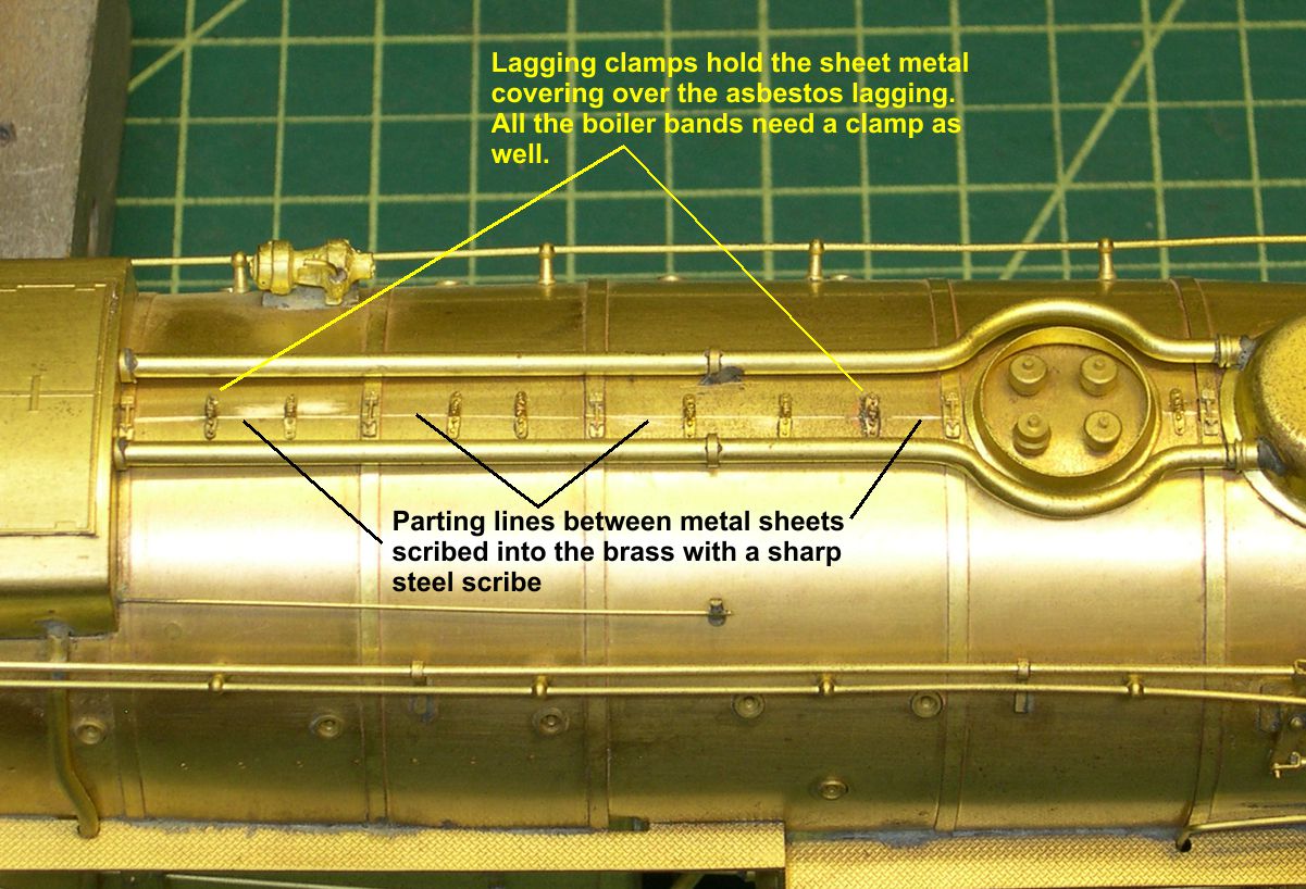
photo 23 ⤵
That concludes the modeling so far. Now for the other discussion. I won’t reveal who asked the questions, but I’m glad they did as it makes for some good instructional moments. One comment concerned my installing the gladhand on the pilot backwards. I’ll bet several people thought that, but didn’t want to embarrass me by mentioning it. I’m glad it was brought up though, because it had not occurred to me to explain that, and there may be several people who do not realize that it is correct. The attached photo titled “Gladhand” shows an as built engine with a nice view of the pilot gladhand.
photo gladhand ⤵
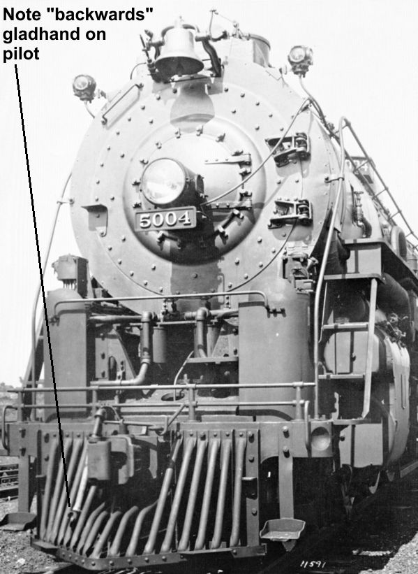
Notice that it points outward instead of inward toward the center of the track. You also need to notice that it is on the left as you face the engine, not the right as when you face a car or tender. That is why the gladhand needs to be reversed – so it will mate with gladhands on cars and tenders. I can’t swear that ALL railroads did it this way, but I do not remember seeing any that did not. I suspect the reason for doing it this way was to avoid having the brakeman stumbling all over the pilot while trying to connect air hoses on the front of an engine. In other words, it was probably a safety feature.
Another thing brought up was shouldn’t I replace those somewhat under detailed smokebox door hinges? Well, I sure would if they weren’t cast integral with the smokebox front. It would require a great deal of careful milling, filing, and sanding to get rid of the cast on ones in order to add nicer castings. Ultimately, I decided that after painting, it just would not make enough difference for me to go to all that effort. I always put things into the perspective of how it will look after painting, as all my models wind up that way when finished. I’ve painted enough models to know what will or will not show up very well after painting. Fortunately, USH got the dimensions real close, and the detailing is fair, so I decided I just couldn’t justify the extreme time involved to change them. Sometimes a little compromise is necessary to actually finish a model in this lifetime, especially when doing two at once.
Another comment was made about what I was going to do about the siderods. ATSF modelers know that the 5001 class had straight rods instead of the large tapered rods of the 5011 class, which the model has. Or do they? The Santa Fe made significant siderod changes to many of the ten engines of this class. I have attached 4 prototype photos illustrating the 3 types of siderods they got. The whole class was delivered with what I refer to as “slab” siderods, just a big flat piece of steel cut to shape with holes drilled in the ends for crank pins. Engine 5008 demonstrates this as built arrangement very nicely.
photo 5008 ⤵

The rods are even painted white making it obvious that the main rod is a tapered, fluted rod similar to the 5011 class, although slightly narrower at the main crank pin end. By the way, white painted rods and valve gear were standard practice on the Santa Fe, especially with slab siderods. The photo of engine 5001 shows a later change to fluted rods, or “I Beam” rods.
photo 5001 ⤵
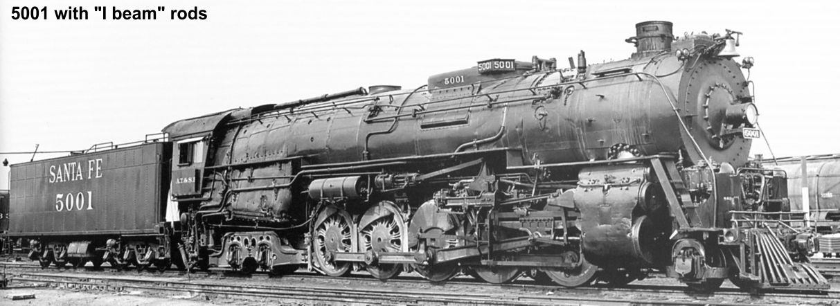
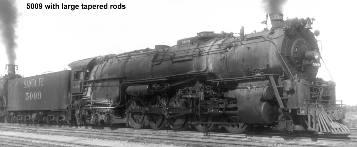
The main rod is the same. I’m guessing that when the war was over, ATSF started using lighter, stronger steel alloys in fluted rods to replace any cracked or broken slab siderods. However, they did not just change over across the board. At least two engines went to scrap with their original slab siderods. Another two went to scrap with the I beam siderods. I have no data on two engines. The other 4 engines got the same large tapered siderods as used on the 5011 class. Santa Fe bailed me out on this one. I can keep the large tapered siderods by just choosing the correct engine numbers to model. The change to tapered rods seems to have occurred around 1950 plus or minus a year. Here’s what I have deduced from photos and timelines: The original rods were probably prone to cracking due to the enormous piston thrust of these huge engines. After the war, better alloys were tried, but even the I beam rods with better materials were not strong enough for these engines. I suspect that Santa Fe had extra sets of large tapered rods made up as backups for both the 5011 and the 5001 classes by around 1950. By that time, the weaker slab rods had been weeded out and the extras were left for the two engines that went to scrap with those rods. Same story on the I beam rods. Extras of those went to the two engines that went to scrap with I beam rods. The remaining engines donated their surviving straight rods to those first two categories and were changed over to brand new sets of large tapered rods meant originally for the 5011 class. So by around 1950, about half the 5001 class had the same large tapered rods as the 5011 class. I happen to love those rods, so I will be modeling engines 5006 and 5009, which photos prove had those large tapered rods. Photos are attached of those two engines.
I also have photos of 5002 and 5004 with large tapered rods. However, the first 5 engines were delivered as coal burners with Buckeye tender trucks. They kept those Buckeye trucks even after conversion to oil. The last 5 engines were delivered as oil burners and had Pullman tender trucks. I happen to really like those heavier, longer Pullman trucks, so I decided to go with 5006 and 5009. One anomaly does appear in the photographic record. Engine 5003 originally had Buckeye tender trucks, but sometime around the time it got I beam siderods, it also got Pullman tender trucks. I can’t find any evidence of a tender swap with another 2-10-4, so maybe it got a tender off a 3400 class Pacific or 3800 class 2-10-2? Anyway, that’s the story of why I am modeling 5006 and 5009 and won’t be changing the siderods.
photo 5006 ⤵
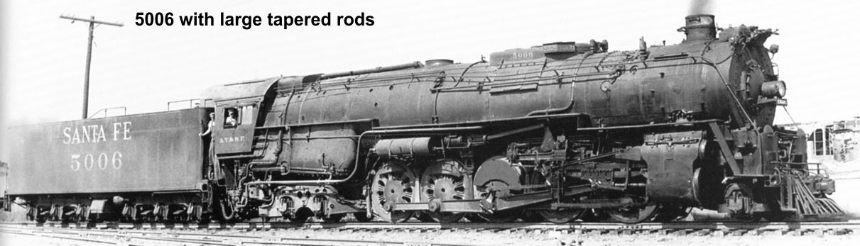
photo 5009 ⤵
Don’t hesitate to question what I am doing or pass along tips. One of the major benefits I have reaped from doing these essays are numerous improved ways of doing things I had not thought of before. I have passed some of those tips along, so others benefit, too.