AT&SF Class 5001 Air Pump Plumbing
There are 17 photos showing how I plumbed up the air pumps and added some miscellaneous detailing around the pilot area. What the photos cannot show is the way I decided exactly how to arrange the plumbing. Unfortunately, no one was considerate enough to take some good photos of the jungle in between the air pumps during the timeframe I model, 1947-1951. The engines had been considerably modified by that time. What I had to do was make a list of what I knew HAD to be in that area between the air pumps. There had to be two intake air filters, since I could not locate them anywhere else on the engine and Santa Fe generally did mount them in there on other classes. Since they cannot be seen at various low angles in photos, they must have been towards the rear of the area and off to the sides where I could not see them in the photos. They of course could not be sitting right on the pilot deck, as one could not remove the filter elements that way. That pretty well pinned down their positions as shown in the photos. The piping was obvious once I knew the positions, since the intakes are at the bottom front on the right pump and the bottom rear on the left pump.
There also had to be two Westinghouse air pump lubricators. Those were initially mounted on top the air pumps as seen in early photos, but during the war they were removed from there. Later, in one set of photos just after the war, I noted they were mounted on the bottom part of the smokebox front. However, in my era, I could see several photos showing the smokebox front clear down almost to the bottom with no lubricators in evidence. What I deduced from that was that the lubricators were moved down onto a bracket just under the bottom of the smokebox where they could project out for filling with oil. Some other late ATSF classes had them mounted this way, so that would be logical. They were probably moved to the lower position so they would not interfere with opening the smokebox front. The oiler lines from the lubricators would be routed towards the air pumps with two lines going to the air pump governor and throttle bodies. I, of course, cannot tell exactly how many lines came out of each lubricator, but 6 from each looks pretty good, so I decided to use that.
Another important feature in the space between the air pumps was a lagged pipe coming from under the smokebox into a pipe tee. The pipe with the tee on it had two globe valves for shutting off the air pumps when necessary and the air pump governor and throttle. This assembly is fairly easy to see in photos, as it is up front, just behind the air pump mounting brackets. This assembly supplied live steam to the air pumps, and the piping is pretty easy to figure out, as part of it is visible and the rest is logical. Having figured out by process of elimination on photos and knowledge of Santa Fe practices what I needed to put in the area between the air pumps, I was ready to dive in.
The first thing to do is to install the air brake pipe for the air hose on the pilot. It has to come first, because it is at the bottom of the stack and would be very tough to install any later. Photo 1 and photo 2 show that pipe installed as well as the two intake air filters.
photo 1 ⤵
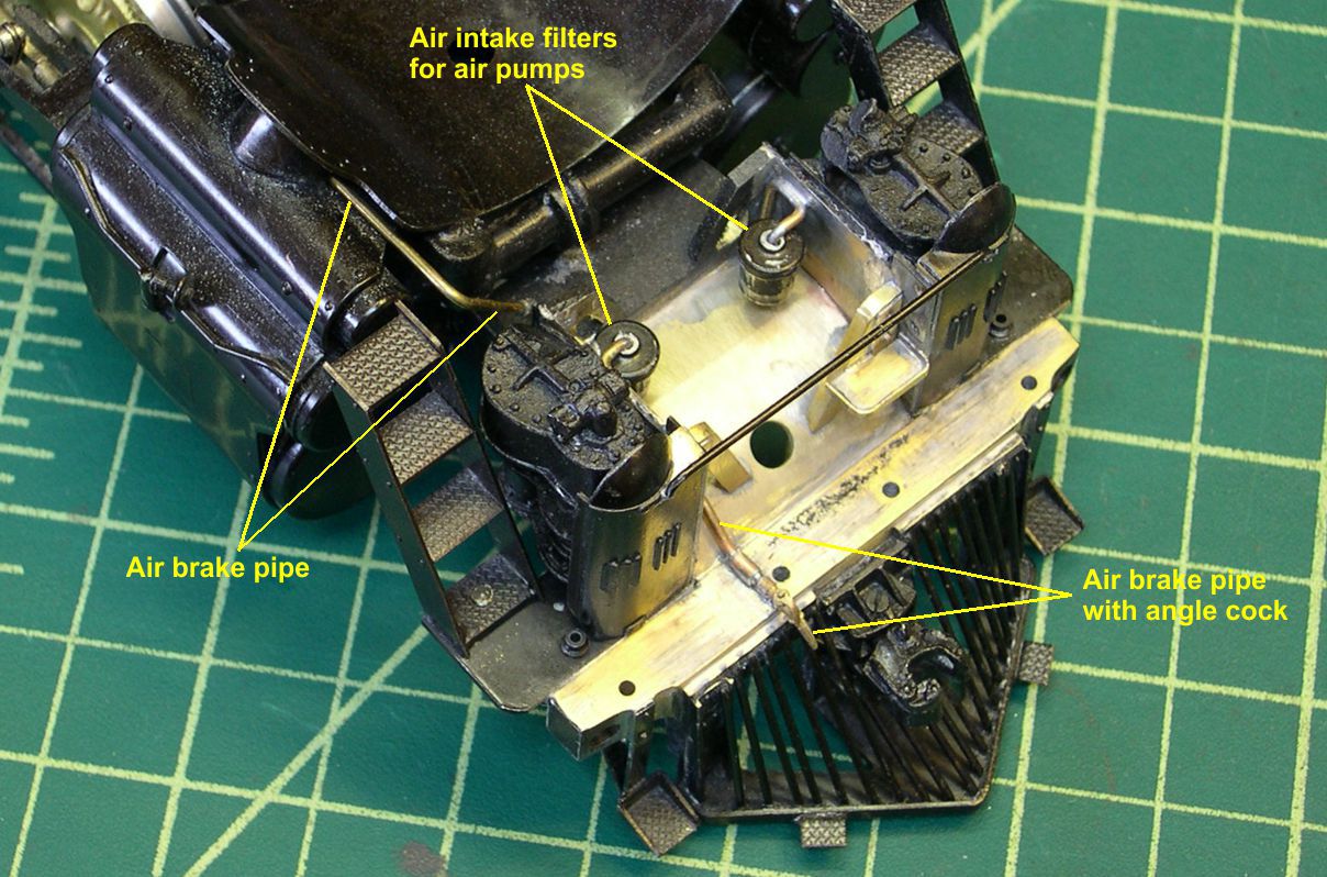
photo 2 ⤵

I re-used the USH filters by cleaning up the residual solder and using correct size piping for them. The detail is crude on those filters, but you can hardly see them once all the detailing is finished anyway, so why waste more expensive castings.? I am just trying to create the impression of the filters being there and these crude ones will do just fine.
In photo 3, I show the preparation of the air pump lubricator castings.
photo 3 ⤵
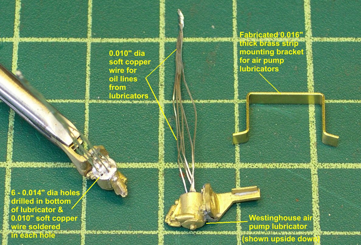
I drilled six 0.014″ holes (#80) in the bottom of each one and soldered in 0.010″ dia soft copper wire. The wire is silver colored because it is pre-tinned wire wrap wire. I have had a tube of that wire pre-cut for many years and always wondered why. Now I know. The reason for using soft copper wire is to duplicate the all bent up, gnarly looking copper tubing used on the real thing. The maintenance guys did not care whether things were neatly routed or not as long as they did the job. Lubricator lines and air control lines tend to be pretty disorderly on the real thing. Half hard brass wire is tough to bend around like that, but soft copper wire just naturally gets all beat up and looks just right.
The lubricator castings came with their own mounting bracket, which I went ahead and soldered on to them, because that would make fabricating a mounting bracket under the smokebox much easier. You can see the soldered on brackets and the fabricated main bracket in photo 3.
Photo 4 shows the lubricators after I soldered their brackets to the main fabricated bracket and then soldered it under the smokebox.
photo 4 ⤵
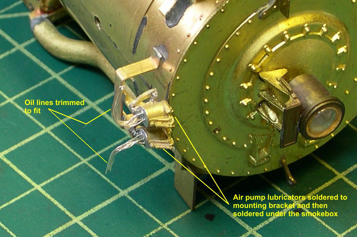
The lubricators need to clear the smokebox front and stick out beyond it servicing as shown in photo 4.
Photo 5 shows how I prepared all the parts for the live steam supply lines to the air pumps.
photo 5 ⤵
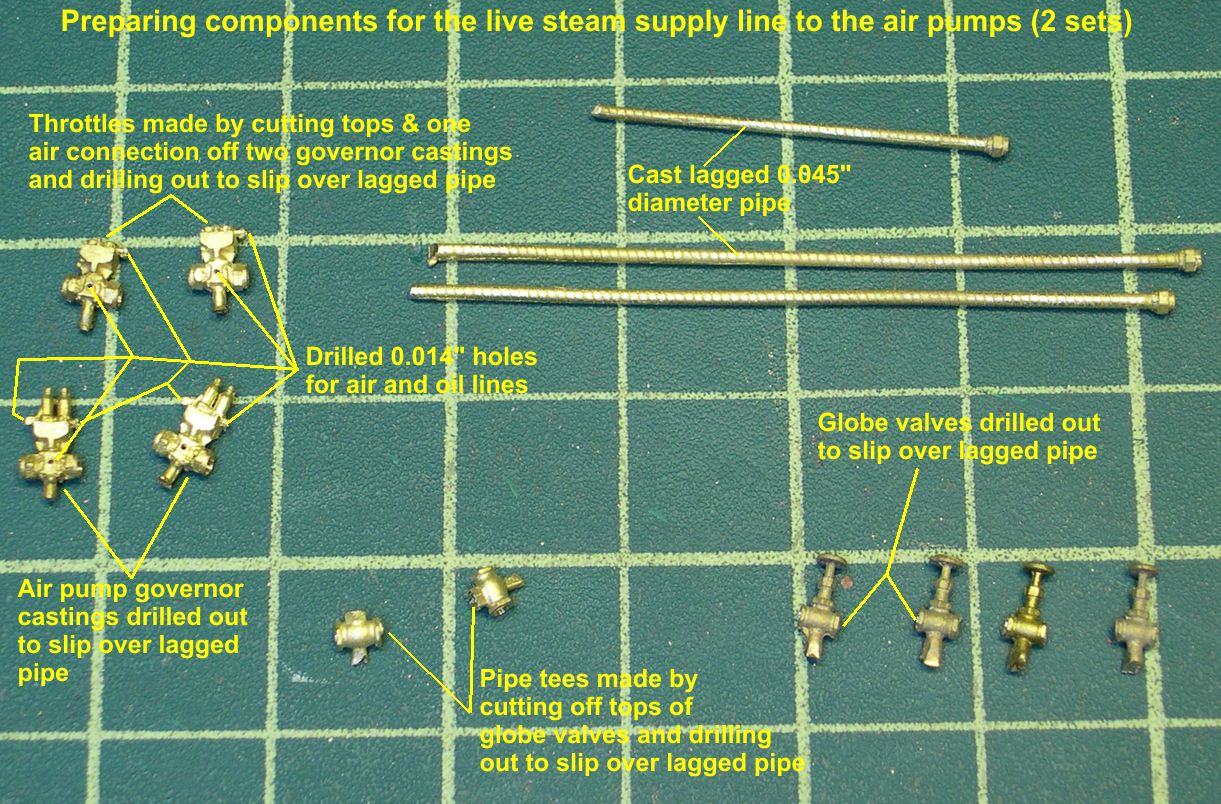
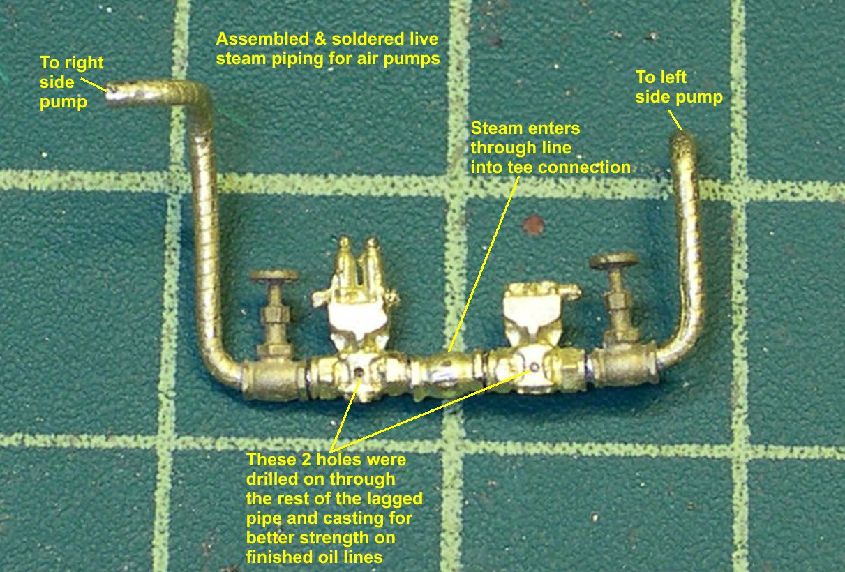
I pre-drilled #80 holes for all the air control lines and oil lines to the governor and throttle before assembly. I also had to drill out the cored holes in each component so it would slip over the lagged pipe. The throttles are not available as castings, but they look just like a governor with the two top projections cut off and one side connection removed. There actually is a very slight size difference in the bodies according to the loco cyc, but not enough to bother anyone, at least not me. Hence, I used two PSC modern AD air pump governor castings for actual governors and another modified pair for the throttles. I did have any pipe tees of the exact size for this lagged pipe, so I located a couple of globe valves the right size and cut off the handles, drilled out the vertical hole, and wound up with what looks like the right sized pipe tee. Photo 6 shows the completed assembly on the lagged pipe.
photo 6 ⤵
I decided I would get a much stronger joint for the small wire by drilling the #80 holes all the way through the bodies of governor and throttle. Doing so also provides some insurance against them rotating on the pipe during subsequent soldering. That proved to be unnecessary, but it’s a minor thing to do. Photos 7,8 and 9 show the steam supply piping installed between the air pumps as on the prototype.
photo 7 ⤵
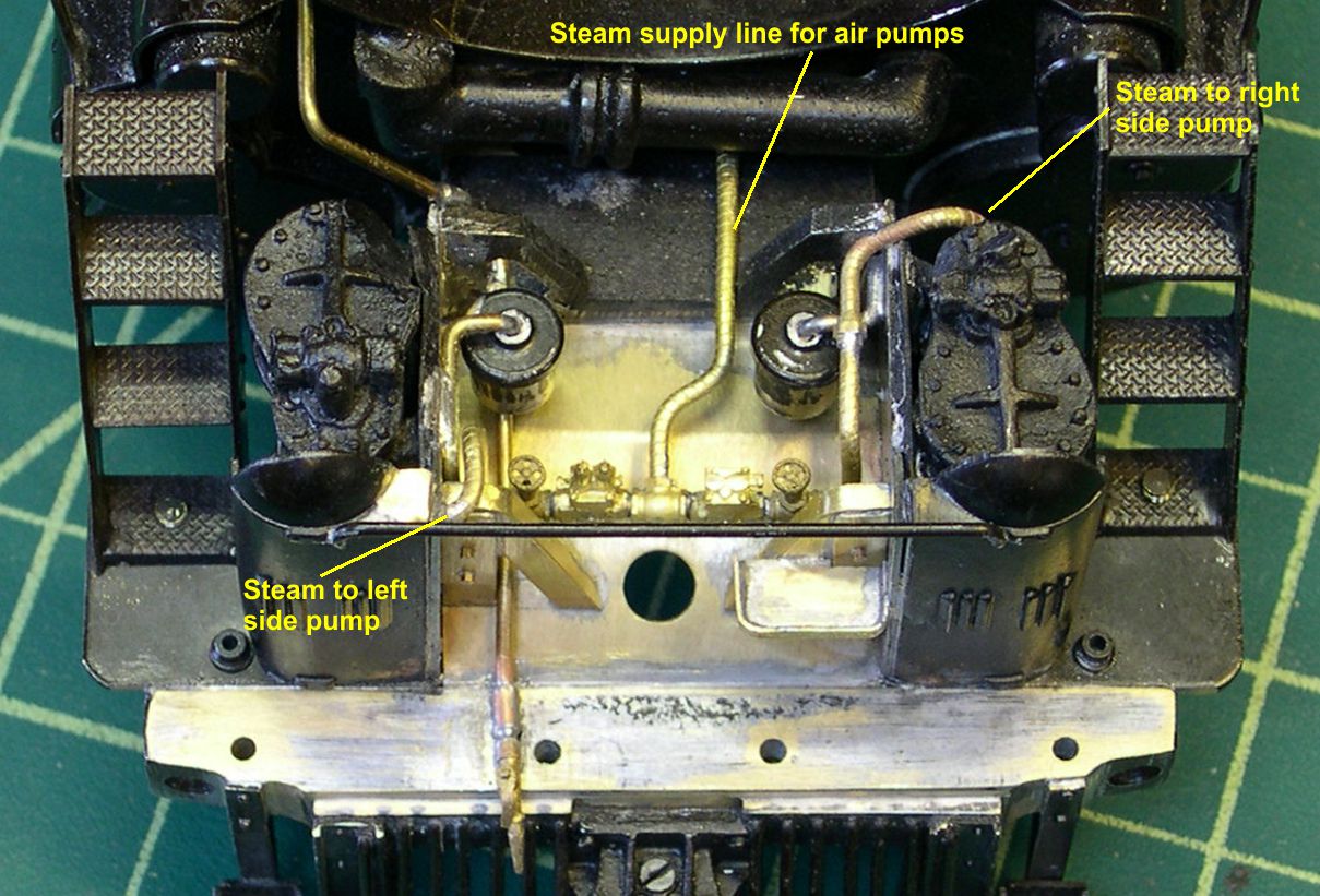
photo 8 ⤵
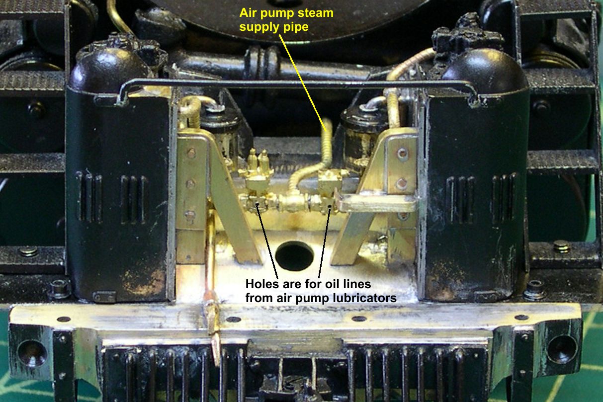
photo 9 ⤵
In photo 10, you can see how I soldered the soft copper wires into the pre-drilled holes in the governor and throttle.
photo 10 ⤵
By drilling the body holes all the way through, I was able to solder those wires from the rear, avoiding any solder showing on the front at all. The wires can then be carefully routed back to logical locations and cut to length. Don’t worry about getting them slightly bent up. That is what the real ones looked like, to. Just don’t totally garbage them is all.
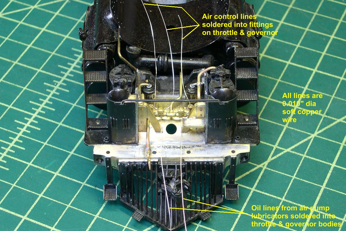
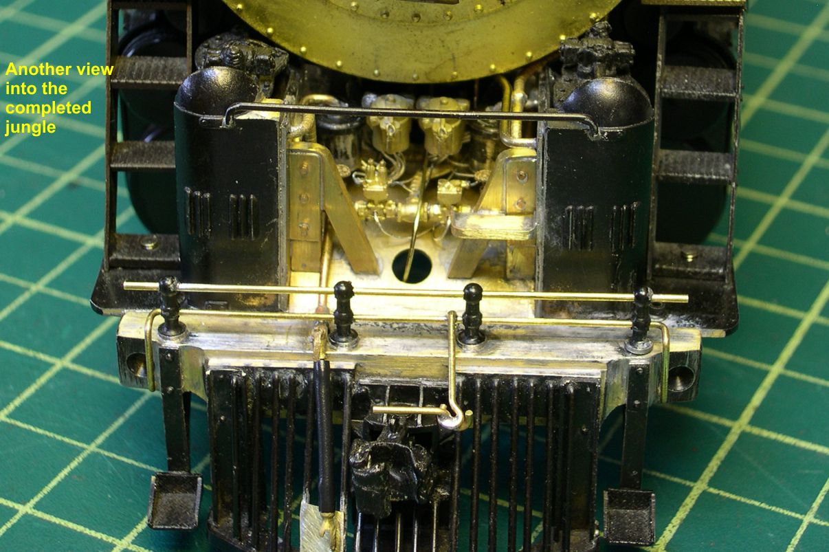
Photo 11 shows how the whole area looks after assembly of the boiler and frame.
photo 11 ⤵

Quite a jungle in there, which is the way the real ones were. I’d bet that the appearance is real close to the prototype. Maybe some photos will show up some day to prove me right or wrong, but for now, I think it’s pretty close and certainly gives the right impression. In photos 11 through 17, there are additional details that have been added to complete the front end detailing of the frame.
photo 12 ⤵
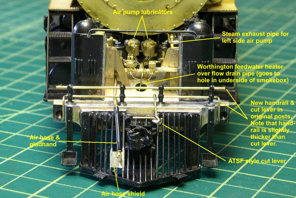
I cleaned up the original handrail stanchions and re-installed them with new handrails and cut levers. The originals were not good representations of those. The Santa Fe used an interesting arrangement of rods on their cut levers as you can see in the photos. Since the smaller horizontal piece will not be inserted into the coupler lift pin, I had to solder it to the slanted piece with the loop in its end. If you envision the joint there as loose and the end of the horizontal rod positioned through a hole in the lift pin on the coupler, you can see how the whole gizmo worked. When you lift the cut lever handle, it raises the slanted bar. The horizontal bar cannot pivot down very much due to that loop in its end, so it raises the lift pin. I actually used this arrangement on my models back when I was using scale couplers with working lift pins. It actually works very well, providing plenty of flexibility on curves, etc. Also note that the handrail is slightly larger than the cut lever in diameter. This is noticeable in photos.
Another detail I added, one frequently missed on models, is the Worthington feedwater heater over flow drain line. Most Worthington SA equipped engines had these somewhere, but it is really obvious on the 5001 class.
photo 13 ⤵
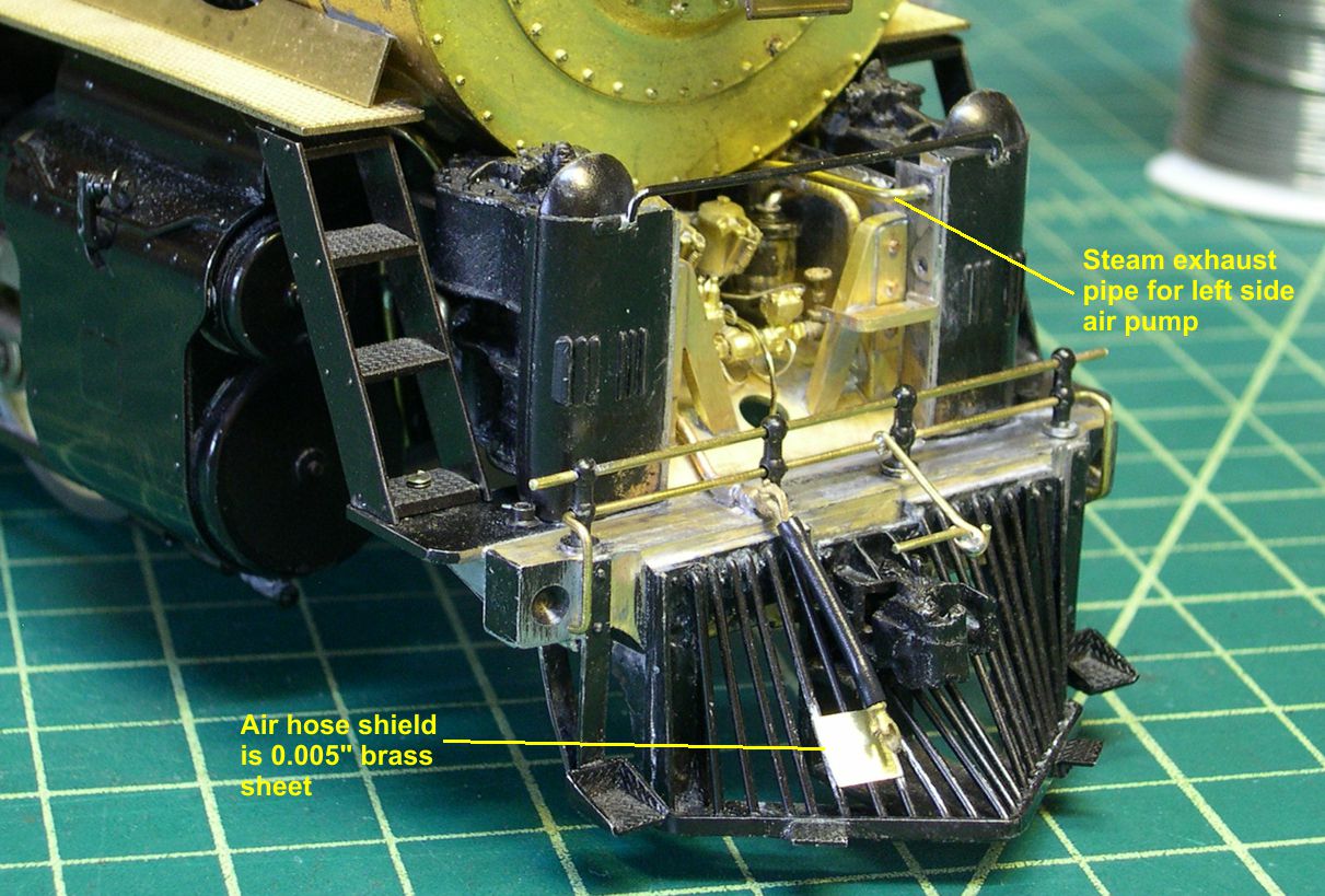
It just runs down through that nice big hole in the pilot deck. Some of the SP GS engines do the same. Most higher speed and modern ATSF engines had the air hose shield I installed on the pilot. It was thin sheet steel and kept the air hose from being driven back between the boiler tubes on the pilot. I cut this one from 0.005″ thick brass sheet and soldered it in place.
photo 14 ⤵
I also installed the air hose and gladhand on the pilot. Also note the steam exhaust pipe running from the top front of the left side air pump.
photo 15 ⤵
It is one of the last things to install, since it is up front and easy to get at.
photo 16 ⤵
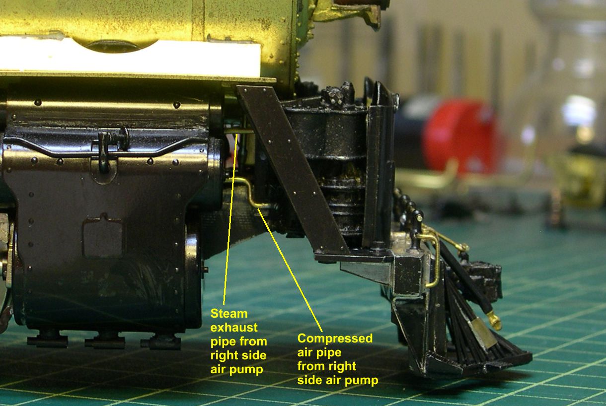
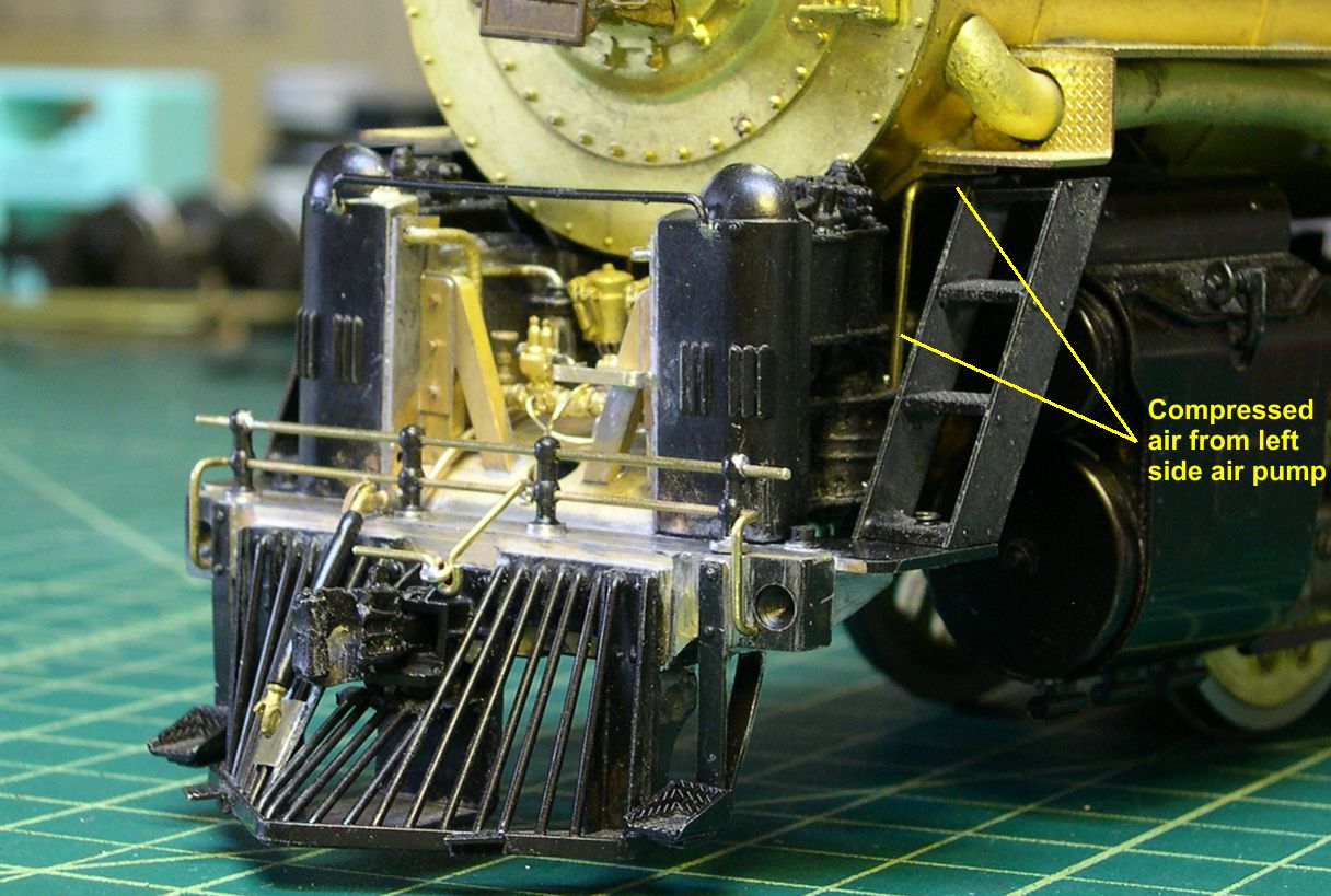
There are several pipes exiting the rear of the air pumps, and they should be there even though they are hard to see without specifically looking for them. They show in some of the photos.
Just to prove I went through all this twice, I included a photo of the two engine side by side.
photo 17 ⤵

Quite a pair already . . .