AT&SF Class 5001 Hot Water Pipe FWH
Sometimes the amount of time and effort expended is not visually very impressive. This segment is a good example of that. There is only one photo and the amount of detailing added is not particularly large. However, this detailing required a lot of time and effort to accomplish. The new hot water pump and its revised position required the large hot water pipe from the FWH to be significantly revised. At this point, I had to revert to the old stereotype of an O Scaler as a blacksmith. This pipe is a big stiff casting that is not interested in being revised in any way. However, it has to be shorter and drop down lower to mate up with the new pump. Compare the attached photo with the earlier “as built” photos to see how much different the pipe has to be.
hot water piping ⤵
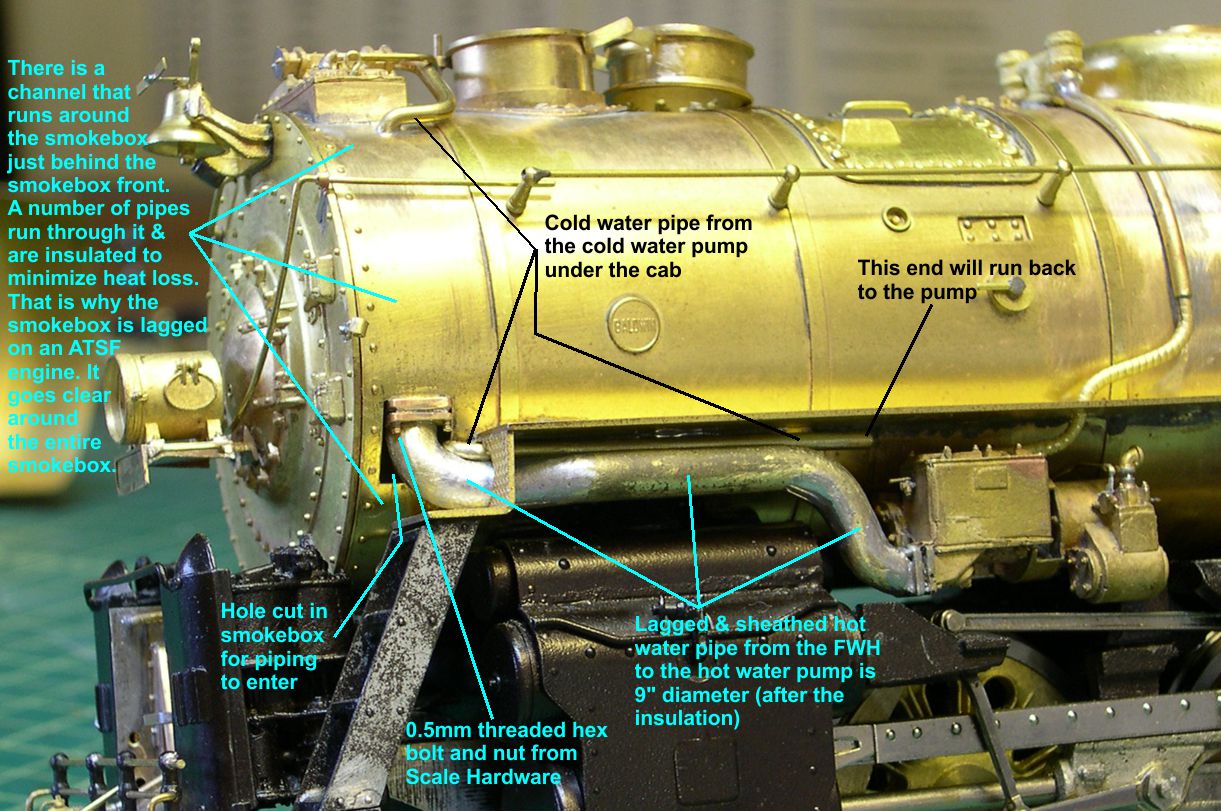
Before attempting the mods to the pipe, it is best to cut the hole in the smokebox to receive the pipe. The lagging and sheathing was not fitted tightly around the pipe as it entered the smokebox, mainly because of the large, square flange joint right at the entry point. I cut the hole by first marking the outlines of the hole on the brass surface based on what I could see in photos. Then I drilled a hole inside the lines and used a small Dremel cutter to rough out the hole. I finished up with fine files.
In order to get anywhere with reshaping the large pipe, you have to anneal it thoroughly. Otherwise, it will just break rather than bending. Heat it up to cherry red and let it slowly cool in the air. I used a propane torch for this. You will probably find it necessary to anneal it more than once as you bend the material. It starts out brittle and work hardens rapidly as you bend it. Don’t get in a hurry or you will break the part. A considerable amount of forceful bending in a large vise, pounding with a hammer, and other blacksmith moves are necessary to get this tough little bugger reshaped properly as shown in the photo. You also have to enlarge the hole between the step and the running board to get a proper fit and allow the cold water pipe to come through there as well. USH did not model the cold water pipe correctly, so they did not run it through that hole.
With the large pipe soldered in place, I made up the large square flange on it by using a slitting saw on my mill to cut the gap between flanges and to cut off the whole part. The two connecting bolts were actually double nutted studs, although I could not see any stud sticking out below the nuts. I simulated what I saw in photos by threading a 0.5mm hex nut onto a 0.5mm hex bolt, then soldering that assembly into a hole drilled at the corner of the flange. The nut and bolt are Scale Hardware items. Since the inside portion of the flange is invisible, I cut the flange in two and soldered one half on each engine.
The cold water pipe was also difficult to fit up due to limited working space for it. Consequently, I only did a short piece of it, soldered that into place and will complete the pipe back to the cold water pump when that item gets replaced.
In figuring out how to proceed from here, it is obvious that I need to remove the cab and rebuild it into a removable one and replace the two big air tanks on the sides. A lot of what has to be done from here on out will involve plumbing around the air tanks and into the cab. That dictates what is to come next. By the way, the air tanks have to be replaced for two reasons. First of all, they are mounted incorrectly too far inside the sides of the running boards, and USH removed some of the tank material on the inside to make that happen. Secondly, the ends of the 5001 tanks were not rounded like the ones on the 5011 class. They were slightly recessed flat ends, so I have to turn completely new tanks for these engines. I have done that before, and it is relatively easy to do.