AT&SF Class 5001 Valve Gear Hanger Support – Damper
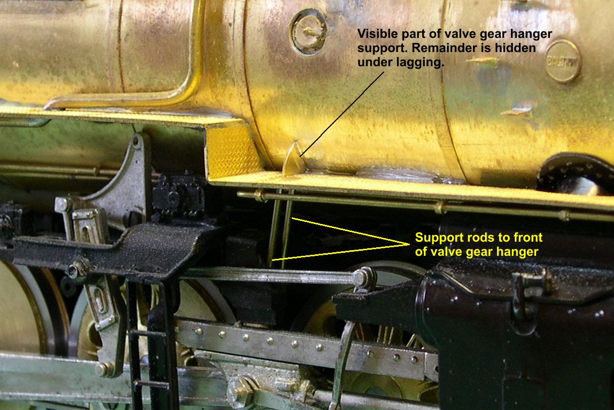
Following the 2014 ATSF Convention in Fresno last week, I am back to work on the 5001 class engines. I have done only two items since the convention, but both required a fair amount of finicky brass work. In photos “Support-1 and 2”, you can see the right side valve gear hanger support bracket.
support 1 ⤵
support 2 ⤵
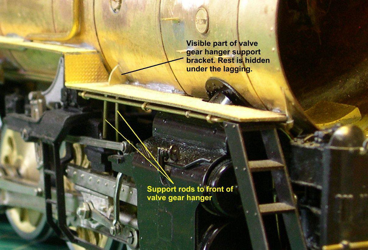
This consisted of a heavy bracket bolted to the boiler with two heavy rods going from it to the front end of the valve gear hanger. The lagging covered most of the bracket, so only the curved stiffening flange above the running board was visible. The two support rods had to be soldered into the running board and positioned so they would just touch the front of the valve gear hanger when the engine is assembled. That way, it looks as if they are connected, but you can still separate the boiler and frame assemblies. The left side had an identical bracket, of course, but it was totally hidden behind the hot water pump, so I did not try to model it.
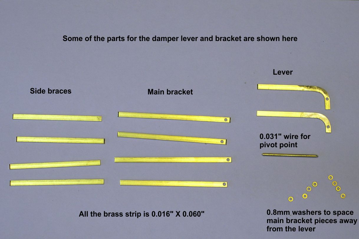
All the big, modern ATSF steam engines purchased after 1937 had an interesting bracket and reach rod mounted just under the running board at the front of the firebox. The handle for the reach rod projected through the running board, so a crewman could walk out along the running board and pull up or push down on the handle to activate something near the place at the center bottom of the firebox where the oil burner entered the firebox. I do not know whether this was some kind of damper control or possibly an oil shutoff. At any rate all the 3460, 3765, 3776, 2900, 5001 and 5011 class engines had it. I have not noticed any retrofitting of it to earlier classes. Photos “Damper-1 through Damper-3” show how that bracket is built up.
damper 1 ⤵
damper 2 ⤵
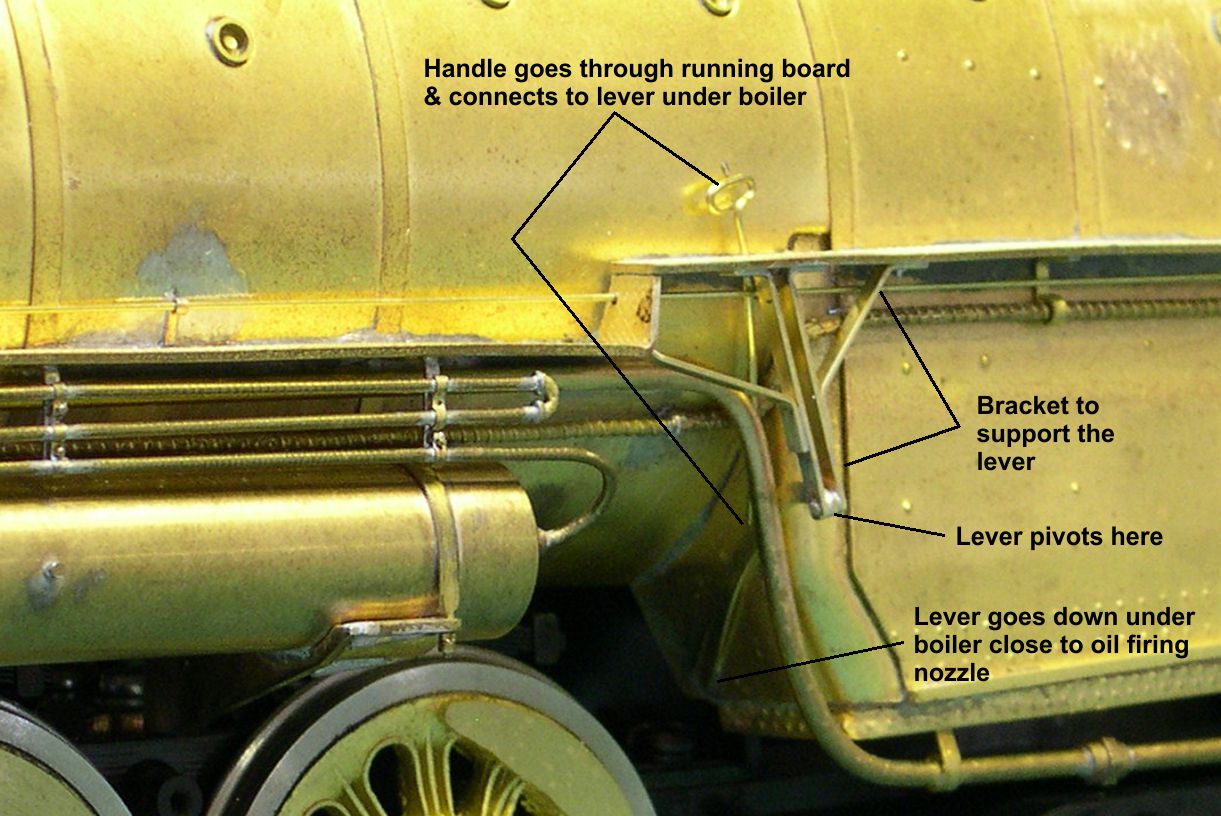
damper 3 ⤵

The reach rod from the handle connects to the lever about 1/3 of the way down the lever so that pulling up or pushing down on the handle raises or lowers the lever down under the boiler where it does whatever it does. The lever pivots on the lower end of the bracket as pointed out in one of the photos.
At this point, there appear to be only 3 things left to do on the boiler assembly, the bell cord and brackets, the passenger steam line with its swivel joints, and the backhead detailing. The first two will make the boiler even harder to handle than it is now without damaging details, so the next essay will cover detailing of the backhead.