AT&SF Class 5001 Air Tanks
There are 8 photos attached to this email showing how I plumbed up the air tanks. As usual, I learned a few new things about the prototype while doing this plumbing and undertook the most finicky soldering I have ever done in doing the cooling coil brackets and clamps. I was relieved when my research showed that the 5001 class only used one set of cooling coils over the large air tank. The 5011 class actually had two sets of cooling coils, one right behind the other. Those are a real joy to fabricate. I made up for the simplicity by going whole hog on detailing the cooling coils though.
In photo 19, you can see the partially completed cooling coils mounted on the brackets.
photo 19 ⤵
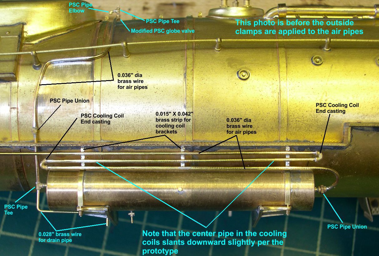
Before you start criticizing me for not being able to keep the pipes parallel, be aware that the ATSF nearly always ran the center pipe at an angle. I assume this was for enhanced drainage of condensed water. While it does not enhance the aesthetics of the engine, it was prototype practice so I had to slant that middle pipe, too. The mounting brackets are just brass strip bent and soldered under the running board. The pipes are then mounted to the brackets with cooling coil end castings joining them at the ends. At this point, I went slightly insane and decided to duplicate the clamps holding the pipes exactly. I was driven to this by finding a nice close up photo of the prototype showing how they did it very clearly. I had never seen this before and had to do it, but what a stupid decision. The amount of time involved is ridiculous and you experience the heights of frustration. All the parts are just so SMALL!
The results of my craziness are shown in photos 20, 21, and 22.
photo 20 ⤵

photo 21 ⤵
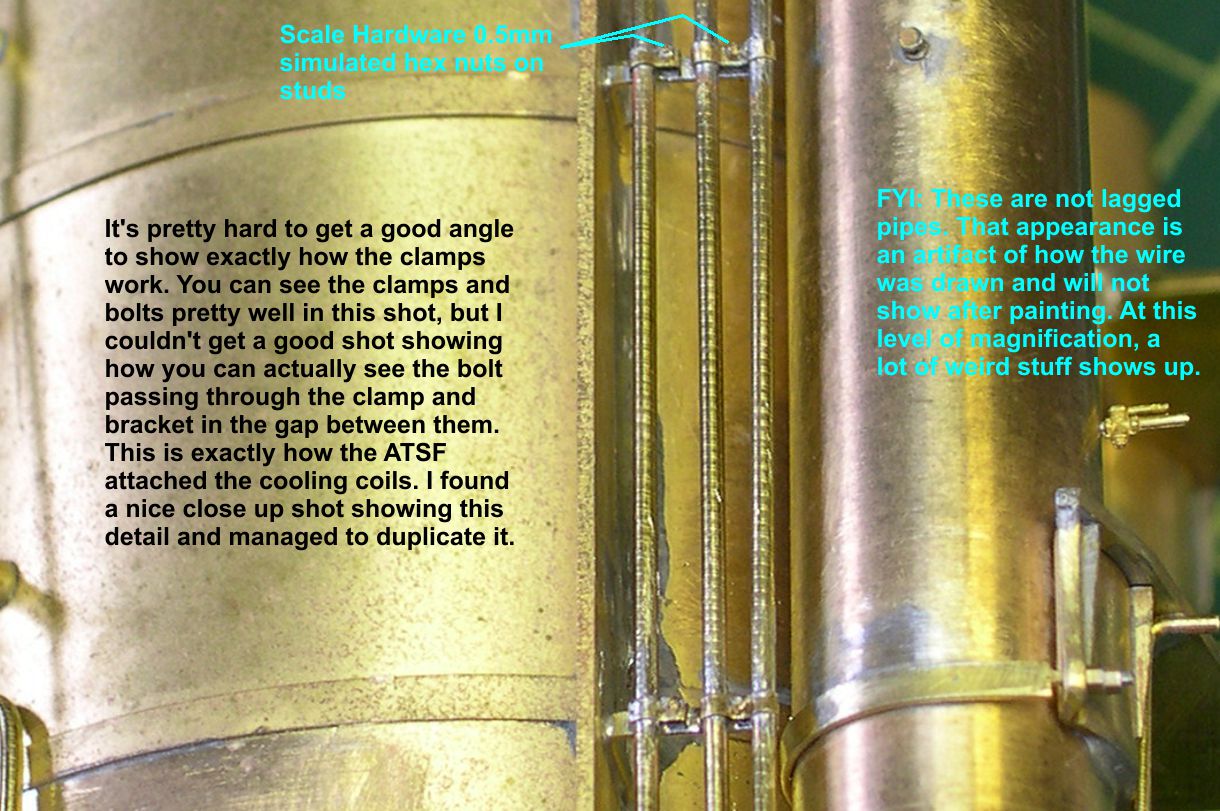
photo 22 ⤵
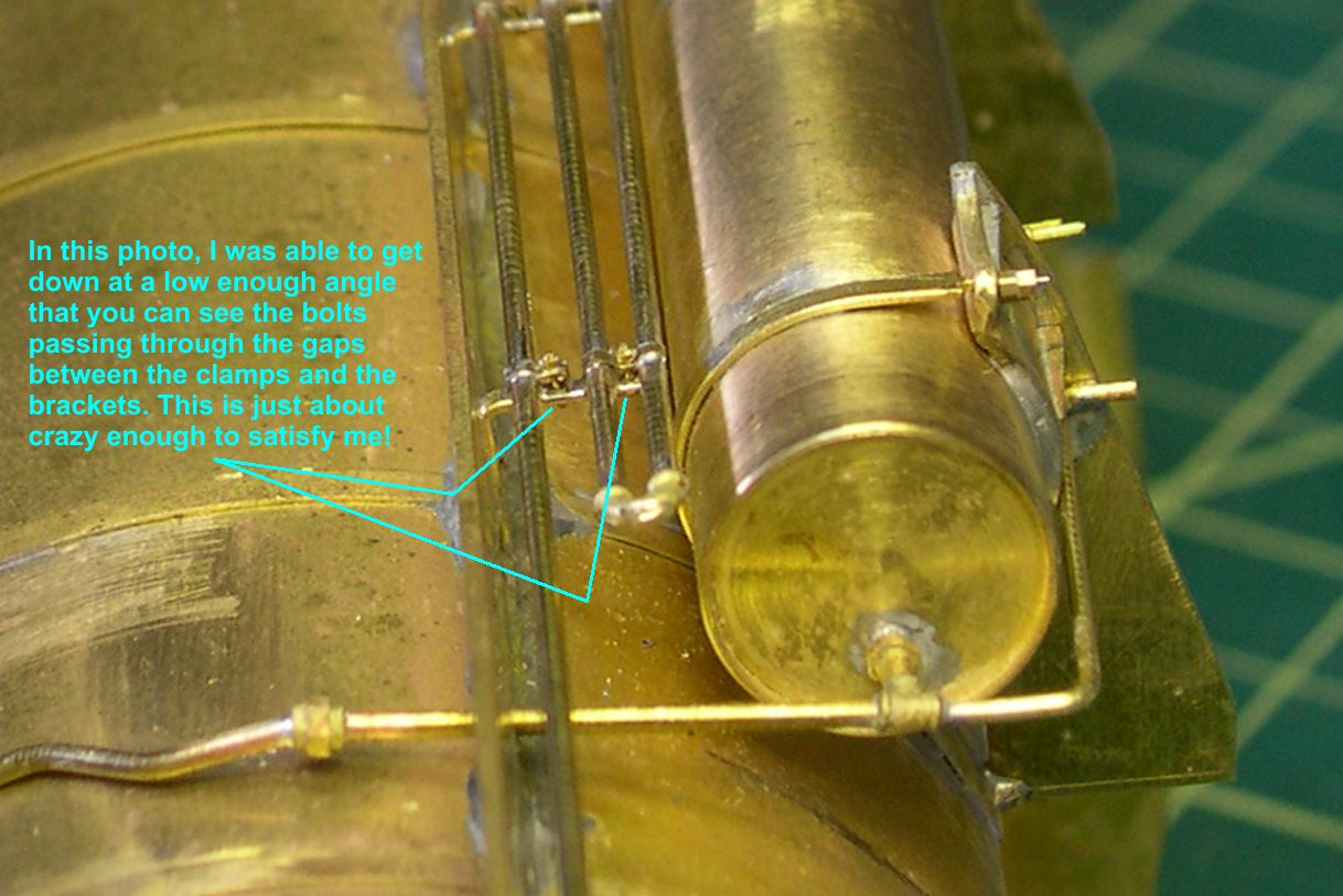
The clamps are made of 0.010″ X 0.030″ brass strip. I bent up at least three times as many as I actually used until I had enough good ones to solder in place. Then I had to drill #80 holes down through the clamp and bracket so I could install Scale Hardware 0.5mm simulated hex nuts on studs. Soldering those in place between the pipes without covering them up with solder was as big a soldering challenge as I have overcome. As you can see in the photos, you can actually see the tiny bolts passing through the gap between the clamps and the brackets. It really looks neat, but was it worth it? I have to hope so. Note that there are two types of clamps. One has two curved ends that fit over the two closer pipes on each bracket and hold both pipes at once. The other type is for a single pipe and has a leg that goes down onto the bracket for leverage.
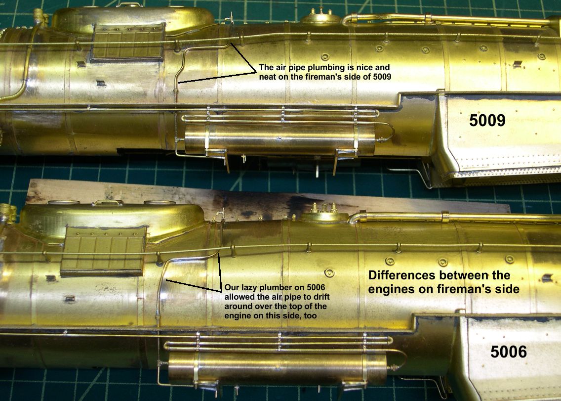
Once I had conquered the cooling coil madness, I was able to move on to more conventional plumbing. I have to watch closely for differences between the two engines, though, as I am trying to duplicate them as closely as possible. I have included a couple of photos showing the differences between the engines in the air tank plumbing. One very interesting difference involves how the pipe running from the large air tank up and over the boiler to the smaller air tank is routed. It looks to me as if engine 5006 was re-plumbed in a hurry, maybe at a roundhouse instead of a shop. Whoever plumbed it was not a fastidious plumber. He just ran the air pipe in a kind of wandering fashion up and over the boiler. engine 5009 has the more usual careful plumbing that runs at nice neat angles everywhere. I suspect that highly experienced shop men grimaced a bit when 5006 went by. Another minor difference is in the drain line plumbing at the front of the short tank. On engine 5009, someone just stuck a drain valve right at the end of the tank instead of running a drain line down under the tank as was normal practice. See photos 23 and 25 for the differences in the two engines.
photo 23 ⤵
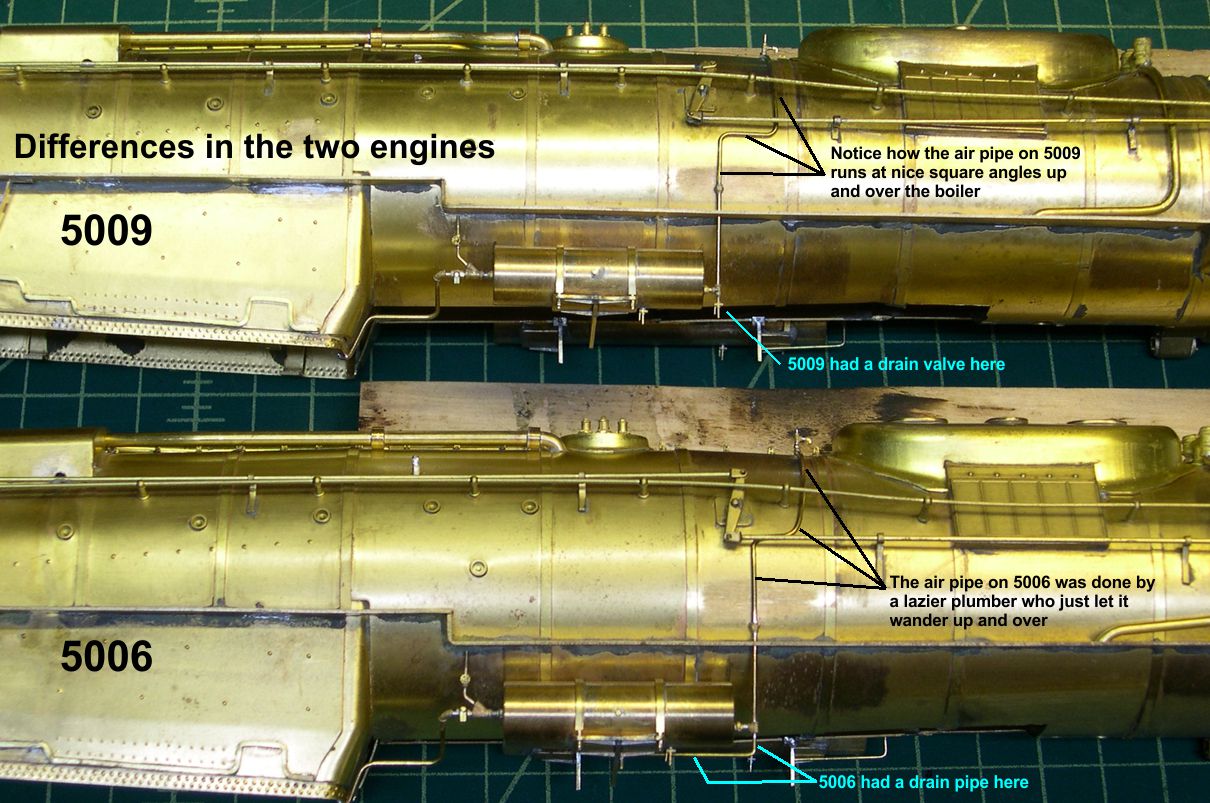
photo 25 ⤵
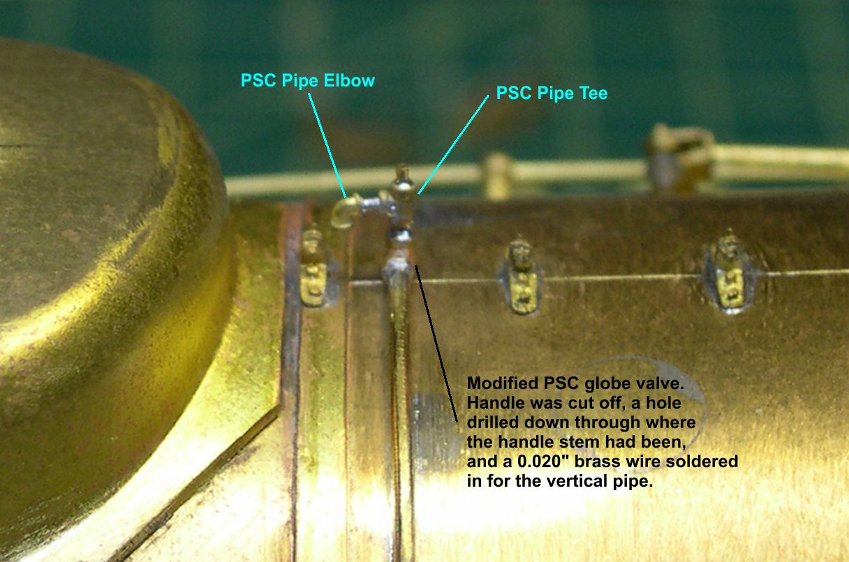
At the back of the small tank, there was some interesting plumbing. Photo 24 shows a close up shot of this area.
photo 24 ⤵
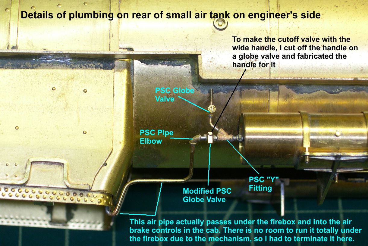
There is no casting for the cutoff valve with the big squared off handle, so I had to use a regular globe valve, cut off its handle, drill a hole where the handle stem was, and solder in a piece of wire. Then I made the fat handle, drilled a hole in one end, and soldered it to the wire. Obviously, this cutoff valve would disconnect the air tank and whole compressed air system from the cab controls. The globe valve above the cutoff valve seems to be just a way to vent the system after cutting it off, as it does not seem to go anywhere. The main air line exiting the cutoff valve ran straight back under the firebox and up into the cab to the air brake controls. However, the compromise of having a big electric motor in the firebox requires me to terminate the line at the firebox, as I could not get the mechanism past the brake pipes otherwise. Oh well, you can’t see those pipes under the firebox in any of the photos anyway, so I can live with that.
Finally, the ATSF generally had some kind of drain or relief valve arrangement in the air pipe over the boiler at the top of the boiler. Sometimes, it was connected to a pipe that ran down under the boiler. On these engines it was as in photo 26.
photo 26 ⤵
One photo I found gave a really good view of it, so I was able to duplicate it pretty well. Adds a bit of interest to the top of the boiler. That pretty well finishes up the whole air tank business, so it is time to move along to some other items.