AT&SF Class 5001 Under Cab Detail
In this installment, I finish the detailing under the cab except for the passenger steam piping that involves 3 u-joints back to the tender. I will leave it to almost the end to avoid damage as much as possible. There are 8 photos attached to this email.
In photo 1, I show how I prepared the drain pipes that exit the cab floor. For some reason, the prototype used back to back pipe elbows to make a slight jog in the two rear pipes just after exiting the cab floor.
photo 1 ⤵
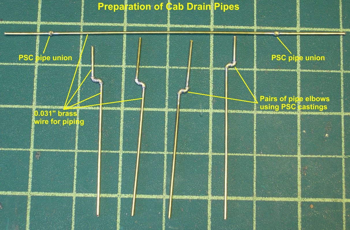
I used PSC pipe elbow castings to make those. The long pipe with two pipe unions by PSC on it is really two drains, one for each engine, that exited the cab floor on the left side and went back under the engine, presumably to dump their effluent between the rails instead of outside the rails. The two rear drains were held to the rear cab support plate by pipe clamps. I made these clamps by crimping 0.010″ X 0.042″ brass strip over a short piece of 0.031″ wire as shown in photo 2.
photo 2 ⤵
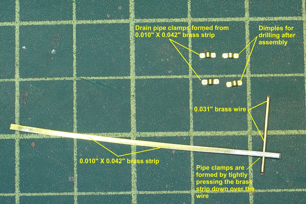
I rounded the ends slightly and punched a small dimple on each end. After the clamps were soldered in place, I drilled through the dimples and on through the cab support plate and installed 0.7mm simulated hex bolts to complete the pipe clamps. Photos 3 and 4 show the drains and pipe clamps installed.
photo 3 ⤵
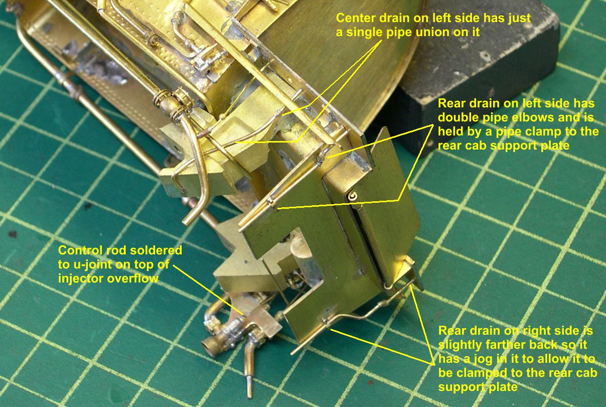
photo 4 ⤵
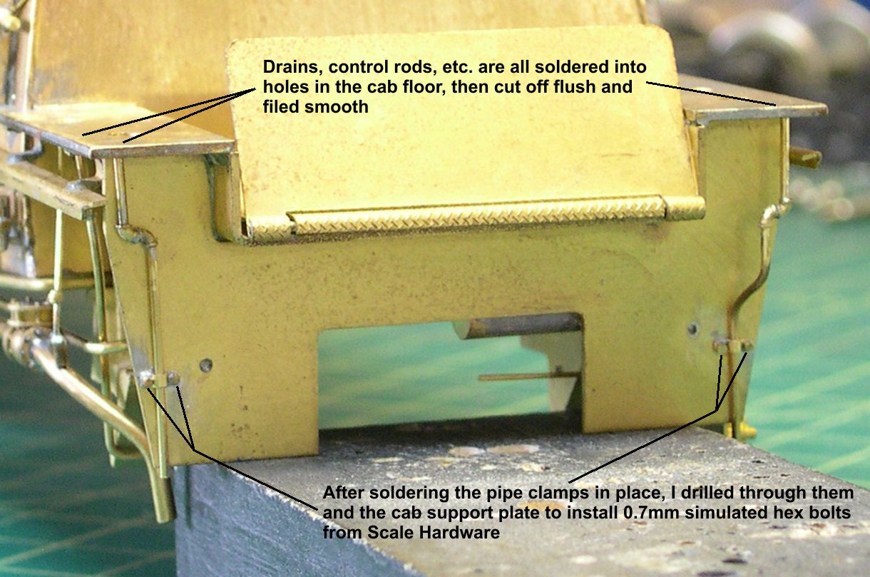
Photos 5 through 8 show all the other detailing installed.
photo 5 ⤵
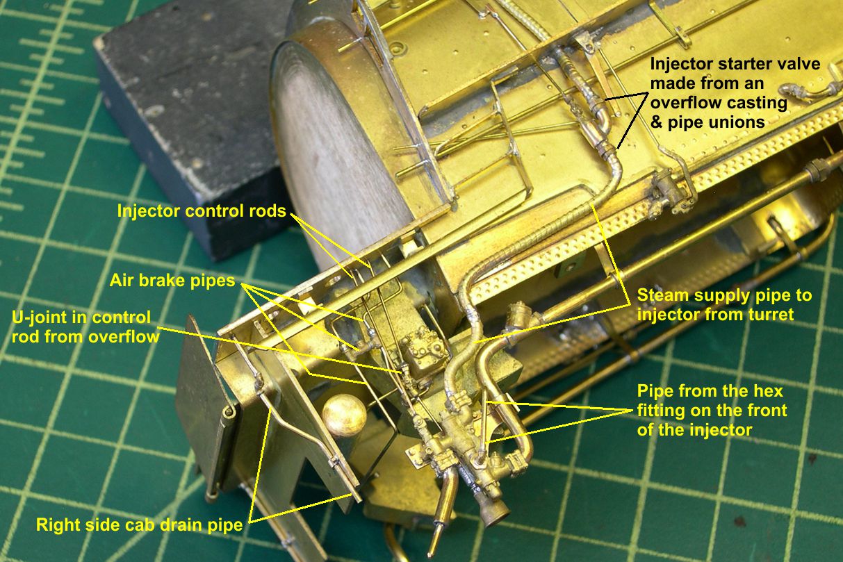
photo 6 ⤵

photo 7 ⤵

photo 8 ⤵

The crossover on the air brake pipes is made from 3 PSC pipe tees. This is easy to see in the photos. Nearly impossible to see is the pair of pipe elbows that connects the air brake piping to the Westinghouse distributing valve. They are pretty much hidden behind the u-joint in the injector control rod from the overflow. I also added the smaller pipe that exits the hexagonal fitting on the front of the injector and goes back behind the injector somewhere.
There is no casting even close to the injector starter valve used on these big Santa Fe engines, so I had to cobble them together using a modified injector overflow, a couple of pipe unions, and some wire. The control rod for the injector starter valve consists of a number of pieces. You cannot see it in the photos, but the little block on the top of the vertical rod from the starter valve is slotted and the flat angled piece slips into it. What is obvious is that the engineer would pull back on the horizontal control rod and the angled piece would convert that to a vertical motion to open the starter valve. The only lagged pipe of the right size for the steam supply pipe controlled by the starter valve is from Wiseman Model services. Unfortunately, it is cast and the castings are really brittle and break easily when bent. I wound up having to piece that lagged pipe together from several broken pieces. I was able to solder it to enough places on the engine that it will not come loose, but it is rather disappointing to run into that type of quality in castings.
I am getting fairly close to finished on the boiler itself. In the next installment, I will add some air piping along the right side and rearrange the small boiler steps on the right side of the smokebox. Onward and upward.