AT&SF Class 5001 Cab
The 15 photos attached to this email show the rebuilding of the locomotive cabs to make them removable and to add correct detailing to them. Having the cab removable makes it possible to do a fully detailed backhead, and you can really see the backhead detail in such large cabs. It also makes painting the engine a lot easier. It may seem like a lot of effort to remove the cab from one of these USH engines and rebuild it to be removable. However, I have done so many times now, and it is really not that big a deal, especially if you are going to do a lot of super detailing on the cab anyway. That’s easier with the cab separated from the boiler.
I used my heat gun to unsolder the elements of the cab starting at the lower right corner at the back. As the back loosened up, I just moved the heat gun around its perimeter until it came out completely. I use some long tweezers to let me gently pull on the part being removed, so when the solder starts to let go, I know immediately and can move the heat along to the next spot. After removing the back wall of the cab, I started applying the heat inside the cab along the bottom of the side. Again, as the solder let go, I moved the heat up along the intersection of the front and side walls. As each part let go, I moved on to the next section. If you react fairly quickly to solder letting go, you can disassemble the cab without actually removing all the parts, as you can see in photo 1, which shows the unsoldered parts right after removal.
photo 1 ⤵
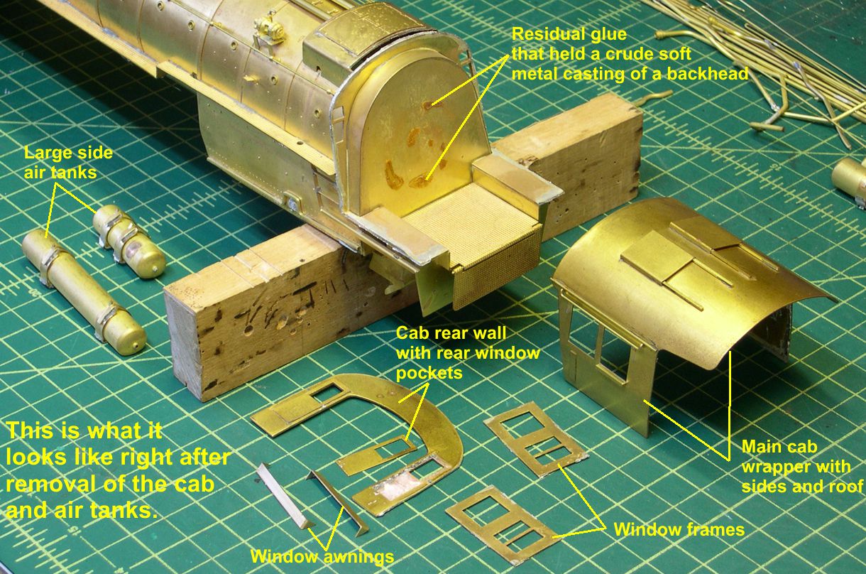
At this time, I also removed the large air tanks under the running boards, as well as most remaining piping and fittings such as the power reverse. As you can see in photos 1 and 2, there is quite a bit of residual solder left on the parts
photo 2 ⤵.
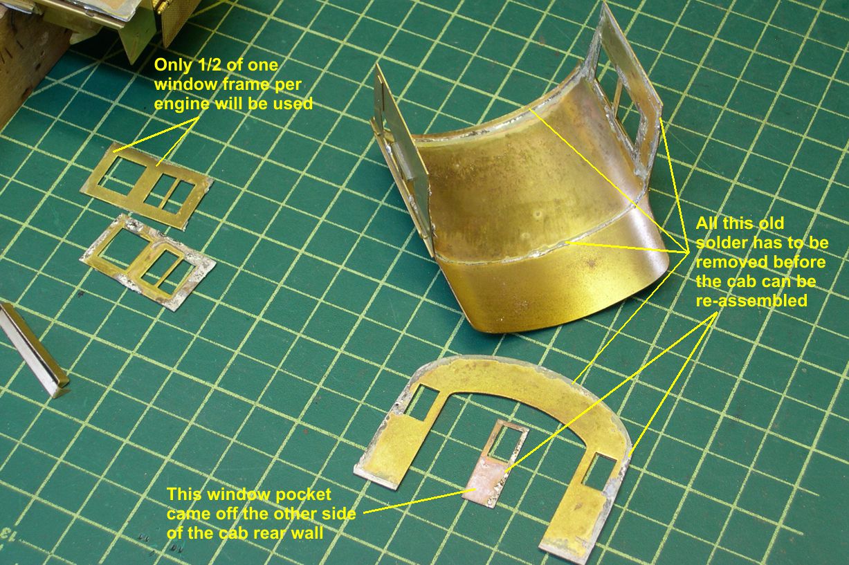
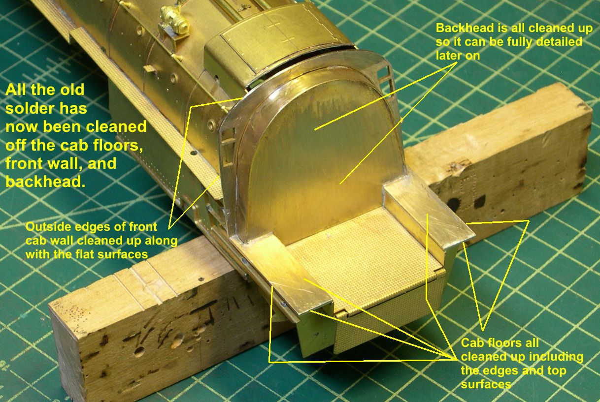
All that needs to go before you try re-assembling the cab, as it will make reassembly very difficult at best. I use an Exacto blade and sanding sticks to remove all the old solder and leave a nice surface for soldering everything back together again.
Photos 3,4,and 5 show how everything looks after cleanup of the old solder.
photo 3 ⤵
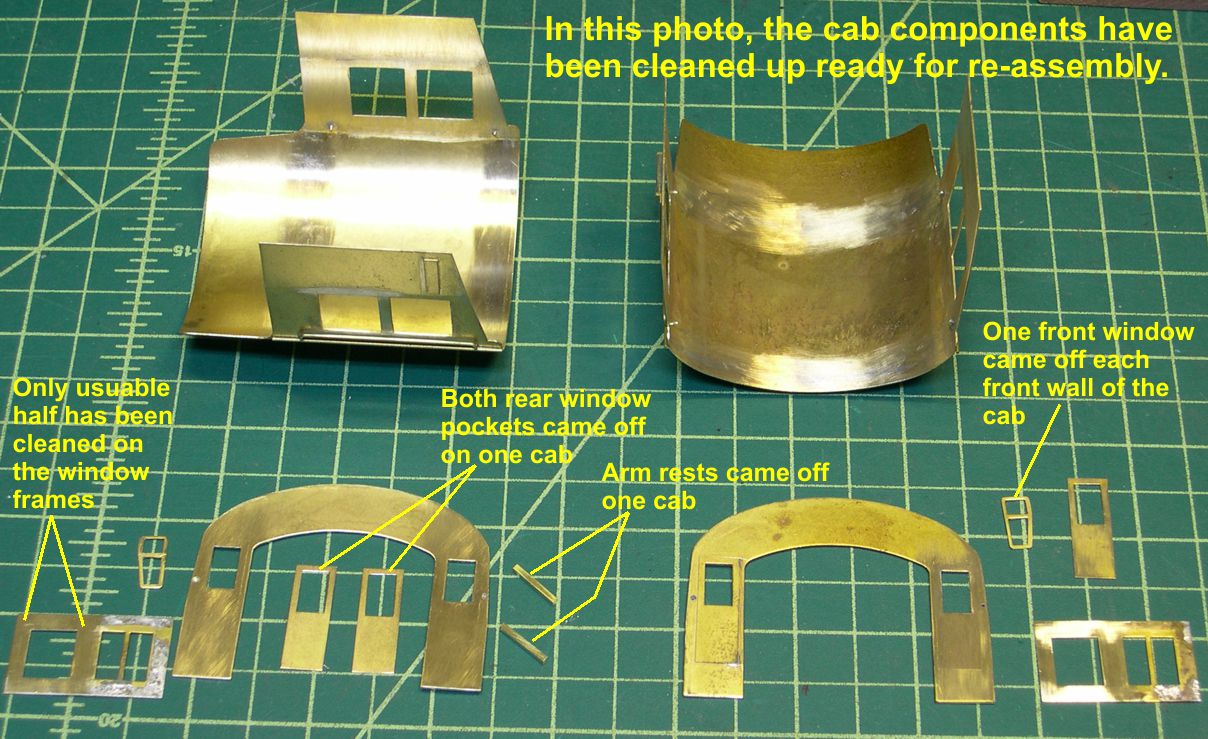
photo 4 ⤵
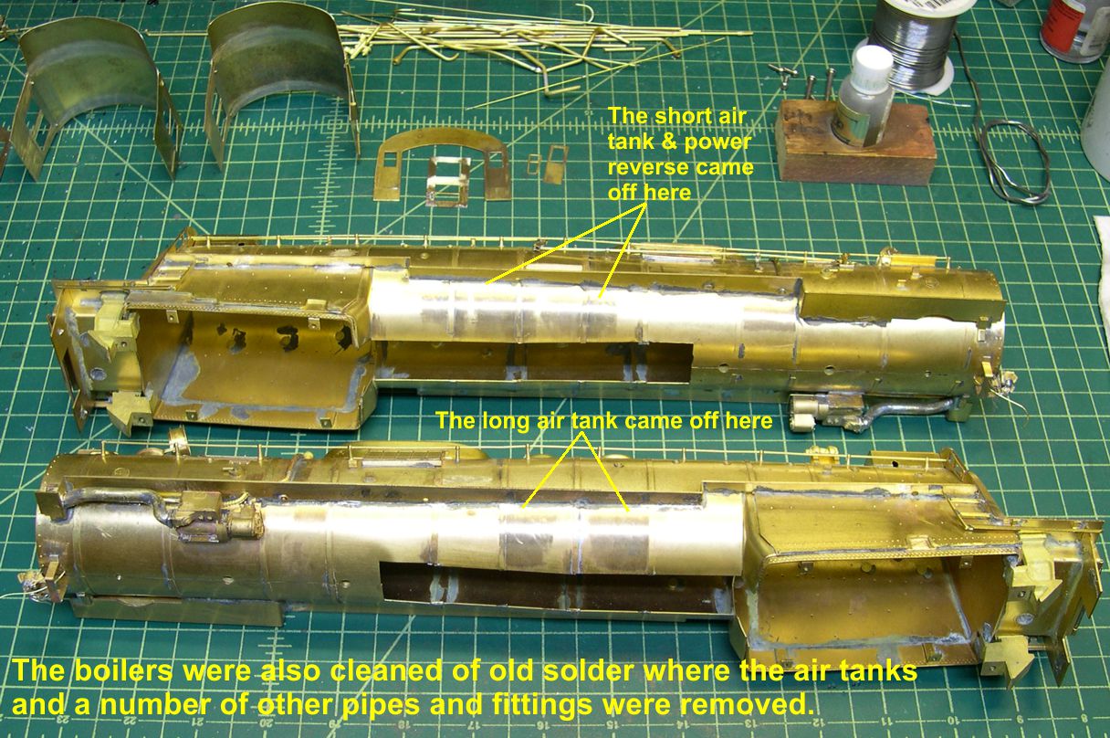
photo 5 ⤵
The next step is to solder the rear wall of the cab back into the main cab shell. I use a couple of brass clamps to help me hold the back wall in position so the sides are flush with the back wall and both sides come right to the bottom of the back wall. Take your time on this step and get everything lined up and steady before trying to solder. Then brush TIX Flux into the joint on the inside of the cab. With a small amount of solder on your iron, touch it to the joint near the center of the roof and move the iron along the joint as the solder flows into it. You can do about 20-30% of the joint on each pass and get a nice clean joint without big solder blobs. I do not even bother trying to remove any excess solder inside the cab at this joint. As you can see in the photos, it is fairly clean anyway, and who can see there after completion of the model? Careful assembly at this stage pays big dividends later, as it pretty well lines everything up for further work. By the way, if something goes awry, don’t be shy about unsoldering the back again and cleaning it all up and starting over. You can do that as often as needed until it’s right. Guess how I know that . . .?
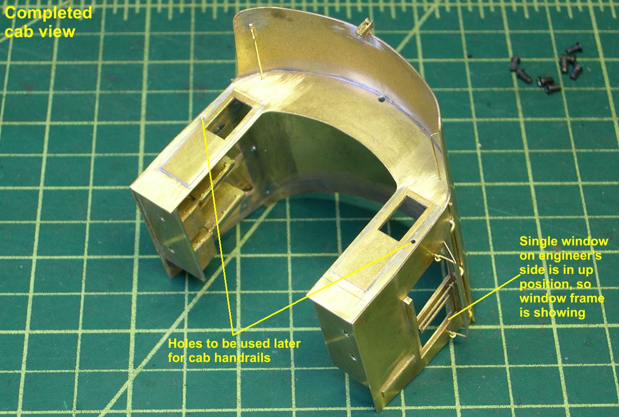
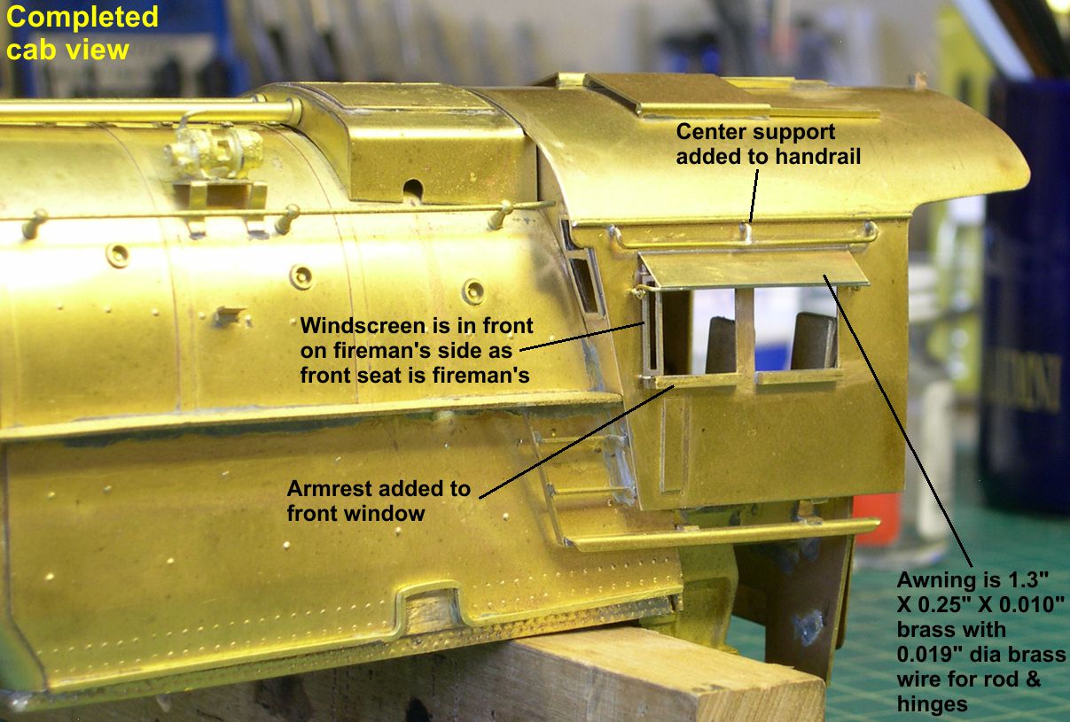
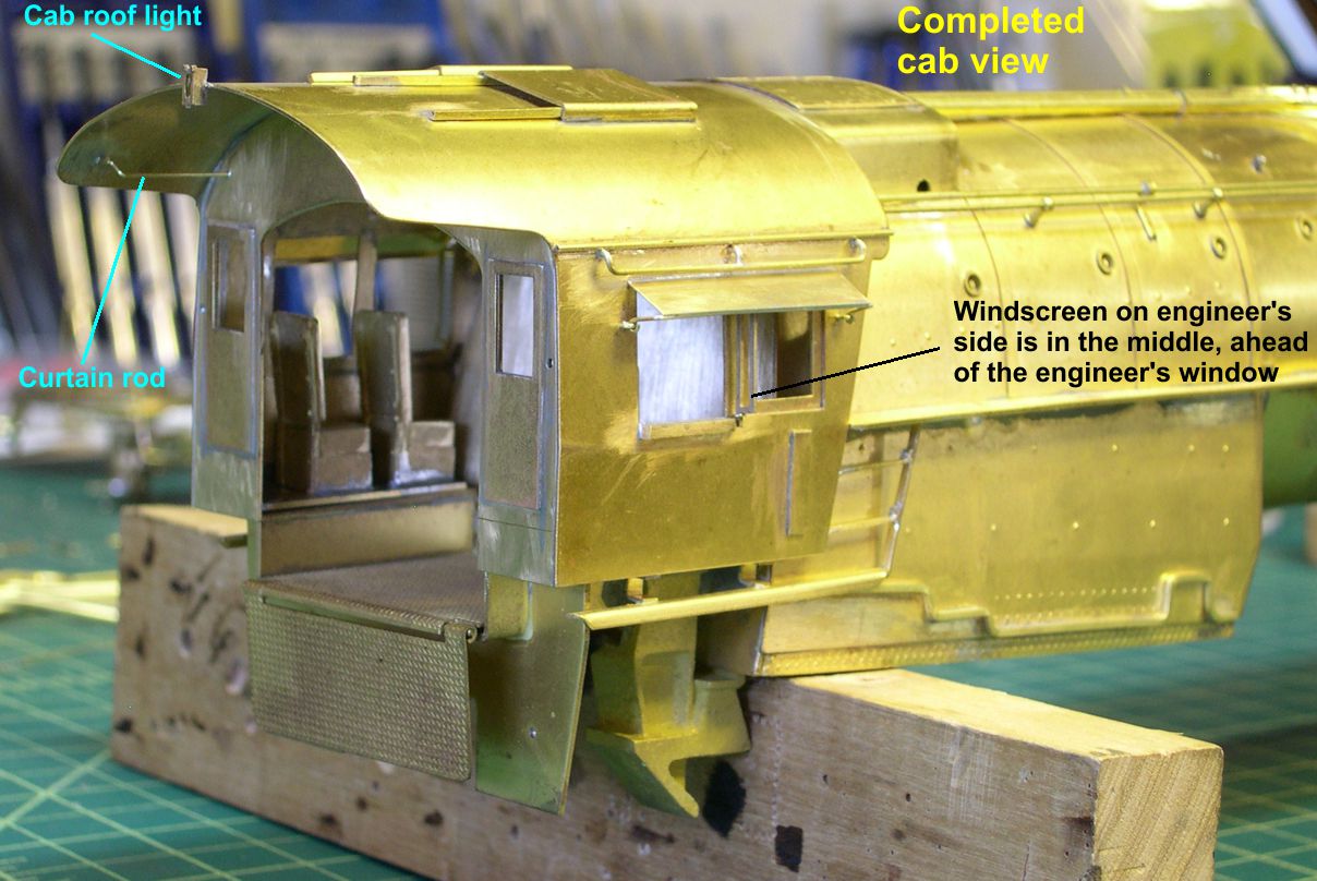
The second step of reassembly is to cut off half of one of the window frames and solder it back into the front window on the engineer’s side. Virtually all photos show this window to be closed, while all other windows are open. This brought up an interesting thing I had not really thought about before. I considered making the windows operate until I realized that there is nowhere near enough room at either end of the window openings for the windows to slide out of sight. Furthermore, none of the photos show partially open windows or one slid over behind the other. The only place they can go to disappear like that is down. Obviously, there must be a pocket below the window openings to lower the windows into. I was then able to confirm that from a couple of cab interior shots. That totally changed my mind about having operating windows. You could spend a long time figuring out how to make that happen, so I just decided to model 3 down and 1 up just like all the photos.
In photo 6, you can see how I did step 3, soldering in false floors to make the cab removable.
photo 6 ⤵
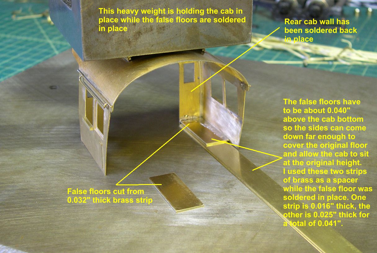
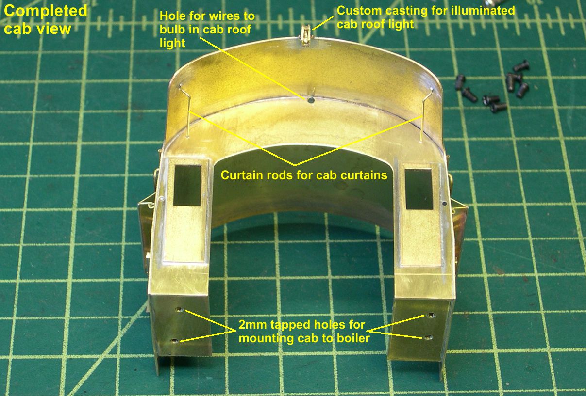
The original floors on the model are about 0.040″ thick. Therefore, I needed to have the new floors about 0.040″ above the bottom of the cab to make the cab sit at the right height. I just used a big weight to hold the cab in place, put two brass strips totaling about 0.041″ in thickness under the false floor to space it correctly, and soldered the false floor in place. These false floors are what I use to mount the cab to the boiler. I hold the cab in place and drill tap sized holes through both the original floor and the new floor at the same time. Try to choose positions for the holes that will not be blocked from access by under cab detailing later. Worse comes to worst, you can always re-drill and re-tap a new hole once you discover your error. Enlarge the holes in the old floor to clearance for 2mm screws and tap the holes in the new floor 2mm. Now the cab can be removed and installed on the boiler at will.
Photos 7-15 show the completed cab from various angles and point out the new detailing added.
photo 7 ⤵
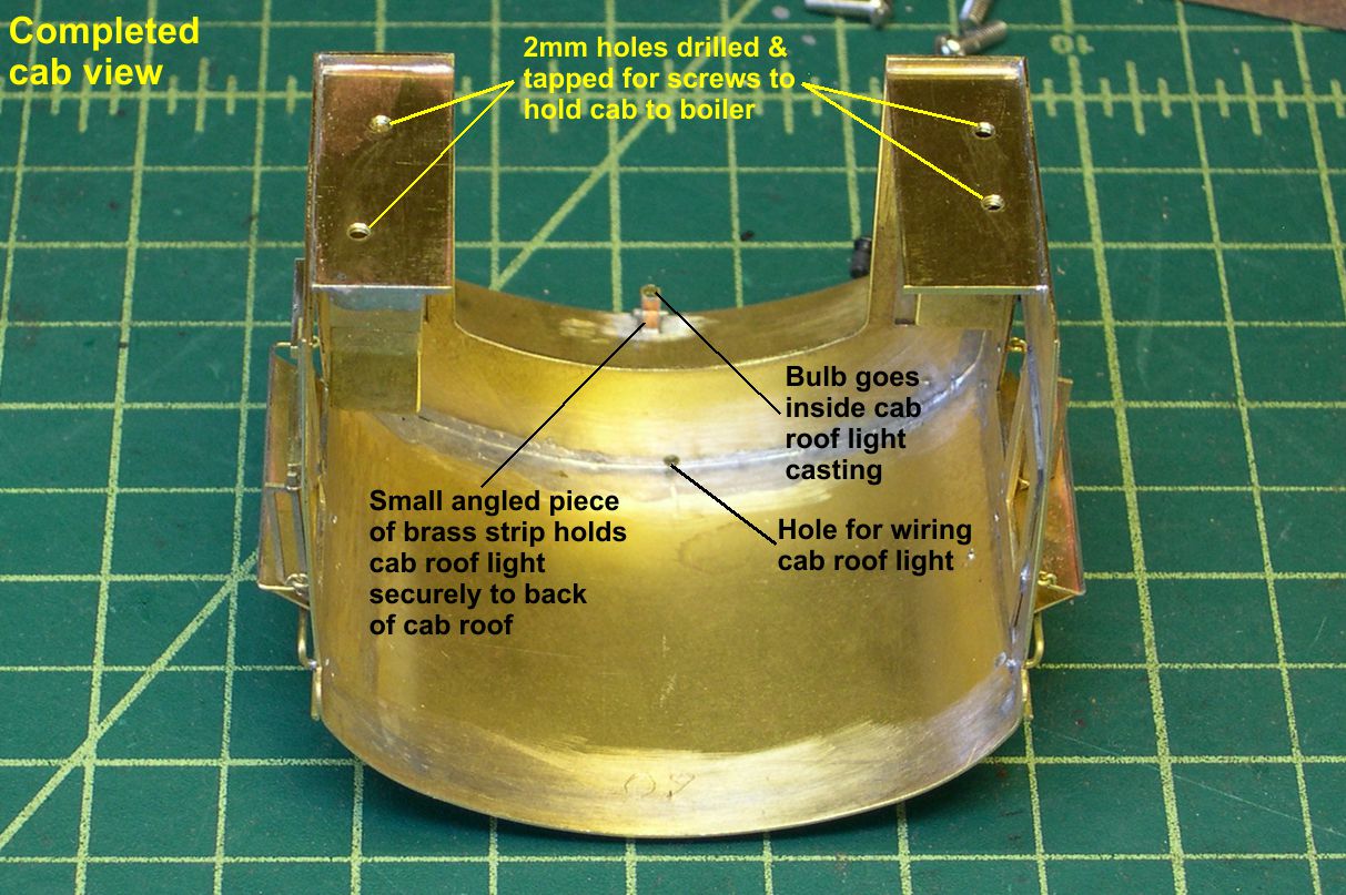
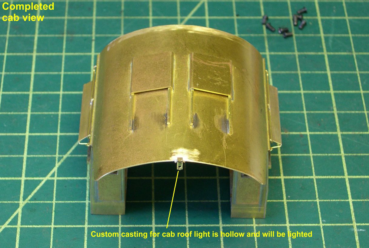
The small cab roof light fixture sits right on the edge of the cab overhang. I have soldered a number of these to the edge directly and never had any trouble knocking them off. However, I decided to use best practices this time rather than show such an “iffy” mounting method. The casting is a custom one I had made up years ago and is hollow so the roof light can actually be illuminated. Run a 0.055″ drill into the hole to make sure a 1.5V bulb will fit with no trouble. Then I bent a small strip of 0.010″ brass into an angle and soldered it to the back of the casting just below the two little bolts that supposedly hold the casting to the roof.
photo 8 ⤵
Carefully determine the center line, hold the angled strip under the roof at the center line, touch the joint with some TIX Flux, and then touch the soldering iron with just a tiny bit of solder on it to the joint. In my case, the solder flowed so quickly that it not only soldered the angle strip to the roof but also soldered the casting to the edge of the roof, all without unsoldering the casting from the angled strip. That happened both times, so I know it’s not a fluke. Must just be a reward for doing it right this time. Note that you also need a hole in the back wall of the cab just under the roof for the bulb wires to the light fixture.
photo 9 ⤵
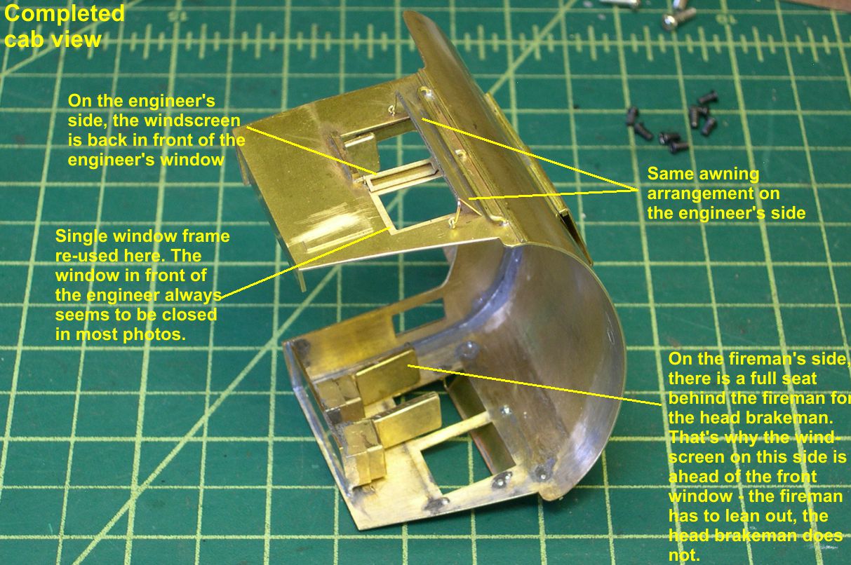
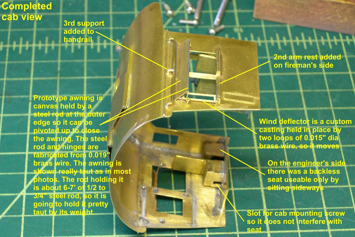
There are 4 seats in one of these cabs. The fireman’s seat is the front one on the left side. Behind that is the head brakeman’s seat. On the right side is the engineer’s seat at the rear window. Behind it is a backless seat that only provides room to sit sideways. I guess the kids getting cab rides had to sit there. I checked the height of the seats against the cab figures from Arttista that I will be using and determined that I needed to remove about 0.070″ off the bottoms of them. I used my new found friend, the disc sander, to do that, and he made very short work of it. The positioning of the seating in these cabs determines where the windscreens on the sides of the cab go. The windscreen casting is another of my custom parts.
photo 10 ⤵
I make little loops of 0.015″ brass wire and solder them into the sides of the cab to act as the brackets for the windscreens. Actually, that’s fairly accurate. ATSF used a casting to do the same thing, but they look much the same. Held this way, the windscreens actually pivot just like the prototype.
photo 11 ⤵
The original awnings on the model were dreadful. I fabricated new ones using awnings cut to size from 0.010″ brass and mounted with 0.019″ brass wire for the rods and hinges. This gives the awnings and their hardware a much more “busy” look and is accurate to the prototype. I also had to make up and add another armrest for the fireman’s window.
photo 12 ⤵

Also, there was a center support on the handrail above the cab windows, so I added that. By the way, You really cannot solder the top of the awning with that handrail in the way, so just unsolder and remove it. After the awnings are complete, you can re-solder the handrail in place.
photo 13 ⤵
Another detail that is seldom modeled is the curtain rods for the cab curtains up under the cab roof. What did you think those canvas cab curtains hung from? Since I install cab curtains on my engines, I need the curtain rods for them.
photo 14 ⤵
I bent those up from 0.019″ brass wire. Now I have to do some research. I just noticed that the ATSF painting and lettering guide claims that the rolled up cab curtain over the back opening of the cab was not common. They specifically point it out as an oddity in one photo. I have been adding it on most of my engines due to the fact that I found the round brackets for it on one or more engines on display. Before I add them to these models, I want to look some more and make sure I know which is correct. I decided not to delay this segment of the saga for that though.
photo 15 ⤵
I may or may not have to add the curtain brackets for the next segment. I have not added the long cab handrails as yet because they can take quite a beating as the model is handled. I will add those near the end of construction.
One note on the last two photos: The cab is not screwed to the boiler. It simply fits so well that it looks as if it is screwed in place. Both engines came out that well. Try that with an imported brass model! A little care in construction pays big dividends.