AT&SF Class 5001 Clean Out Lids – Throttle
I’m baa-ack . . . After a month’s hiatus, I’m back to working on the ATSF 5001 class models. I had to put the project on hold to help Key get their drawings corrected for the FT project. The designers in Korea had gotten themselves all messed up and really didn’t know how to work their way out of it in a reasonable amount of time, so I had them send me the CAD files and I fixed them directly. It was a bit grueling but we have it all fixed up now and both the FT project and my 5001 project can get going again.
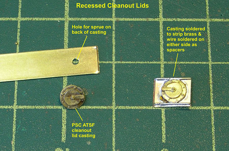
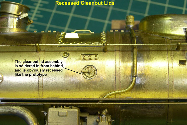
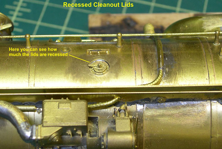
Some of you unfamiliar with ATSF engines may not know that the smokebox was lagged on ATSF steamers, just like the rest of the boiler. That means that having the cleanout lids mounted on the outside of the smokebox is incorrect. They should be recessed below the lagging surface. To do that, I soldered new PSC ATSF cleanout lid castings to some brass strip, then soldered brass wire pieces on either side of the casting to space it back from the opening in the smokebox. I documented how I did this in photos “Cleanout Lids-1, 2, and 3”.
clean out lids 1 ⤵
clean out lids 2 ⤵
clean out lids 3 ⤵
What I did not document was the cursing and swearing as I tried to get the assemblies soldered in the right positions. I should have thought the whole thing through better, but it’s done now and looks fine, so I won’t waste any more thought on it.
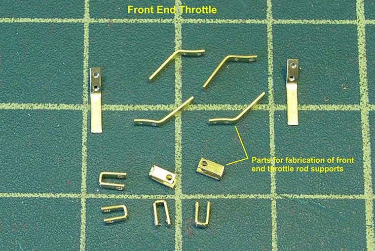
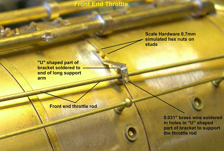
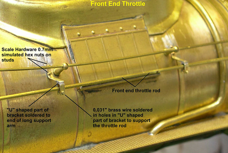
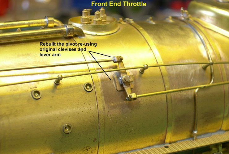
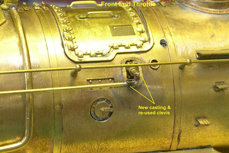
The next item was the front end throttle. The pivot lever was actually pretty well done, as were the clevises on the rods. However, the support brackets were not even close. After studying photos, I determined that the brackets consisted of the support arm with a “U” shaped bracket on the end through which the throttle rod passed. There was a smaller roller assembly at the bottom of the “U” shaped bracket. The rod actually road on the rollers. The FT issues were just breaking as I got into making these brackets, so I did not get everything documented as well as usual. I will have to describe some of the fabrication instead. The “U” shaped brackets were the hard part, as it is very difficult to get a really sharp bend in strip brass – a nearly square bend as desired here. I was able to achieve it after some trial and error by holding a sharp chisel at the bend point and giving it a light tap to drive the chisel about half way through the brass strip. I could then bend the brass strip very sharply as seen in the photos “Throttle-1 thru 5”.
throttle 1 ⤵
throttle 2 ⤵
throttle 3 ⤵
throttle 4 ⤵
throttle 5 ⤵
Holes were drilled for 0.031″ brass wire in the “U” bracket to simulate the small rollers. As seen in the photos, I used Scale Hardware 0.7mm simulated hex nuts on studs to finish off the mounting of the brackets. I added some detail to the pivot lever, like the arm that comes over the pivot, and replaced the front end casting with a better one.
