What’s on the workbench October 2021
Terminal Boards for the Edge of the Layout
I am rewiring my layout after another move for DCC and CMRI signaling. To minimize the difficulty working under the layout I am building terminal boards and mounting them on the edge of the layout. Hinges make it possible to swing the circuit boards under the layout and hook them up under the layout. For adjustment and troubleshooting the boards can be swung down and even secured in extended position.
These pictures illustrate how the boards are used. Each board has places for electrical terminal blocks, electronic equipment, jacks for connecting layout equipment and plug connections. The plug connections are for track power, signal power, CMRI communications and lighting power. By using plug connections a lot of the terminal board wiring can be done at the workbench instead of at the layout.
After building several of these terminal boards I have a basic standard. I use basswood from the big box stores as it is relatively soft and does not splint when installing small mounting screws for mounting equipment. Here is the list of parts.
Basswood:
1” x 2” x 16” Two legs for the terminal board assembly
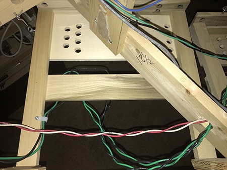
1/2” x 6” x 16” Terminal Board electronics and power buses. Drill 5/8” wire holes using a Forstner drill.
1/2” x 3” x 16” Terminal Board for track power and power buses.
1/2” x 3” x 16” Terminal Board at front edge for electronic equipment. Drill with 5/8” Forstner drill.
3/4” x 4” x 3-1/2” Two wood blocks for hinge attachment
Hardware
One pair 1” hinges with removable pins
One hook and eye 2-1/2”
Wood Screws #10 x 1” flat head Phillips 8 per standard terminal board
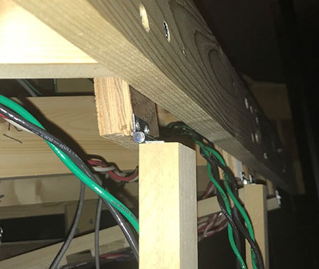
Hinge Position
Basic Terminal Board
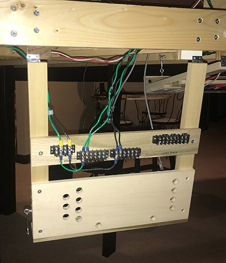
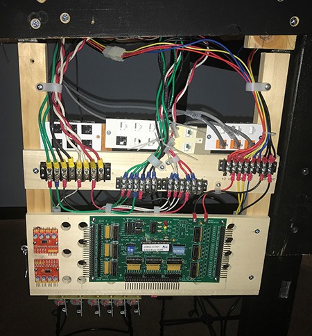
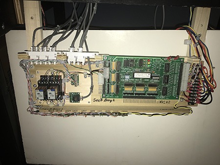
Hooked Under Layout
Hooked under layout
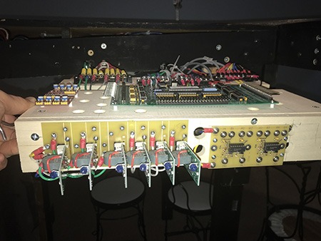
Mounted Edge Equipment
Mounted Equipment
Partially wired
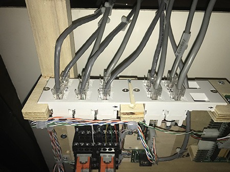
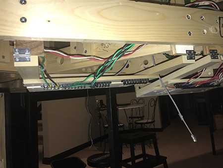
RJ SW Control and Signal Jacks